Accumulator plate grid surface drying kiln

A surface drying, battery board technology, applied in lead-acid battery electrodes, drying gas layout, progressive dryers, etc. Effect

Pending Publication Date: 2019-02-01
TIANNENG BATTERY WUHU
View PDF8 Cites 2 Cited by
  • Summary
  • Abstract
  • Description
  • Claims
  • Application Information

AI Technical Summary

Problems solved by technology

The surface drying device of the battery grid cannot control the temperature well, resulting in waste of energy

Method used


Image

  • Accumulator plate grid surface drying kiln

Examples


Embodiment Construction

[0011] In order to deepen the understanding of the present invention, the present invention will be further described below in conjunction with examples, which are only used to explain the present invention and do not constitute a limitation to the protection scope of the present invention.

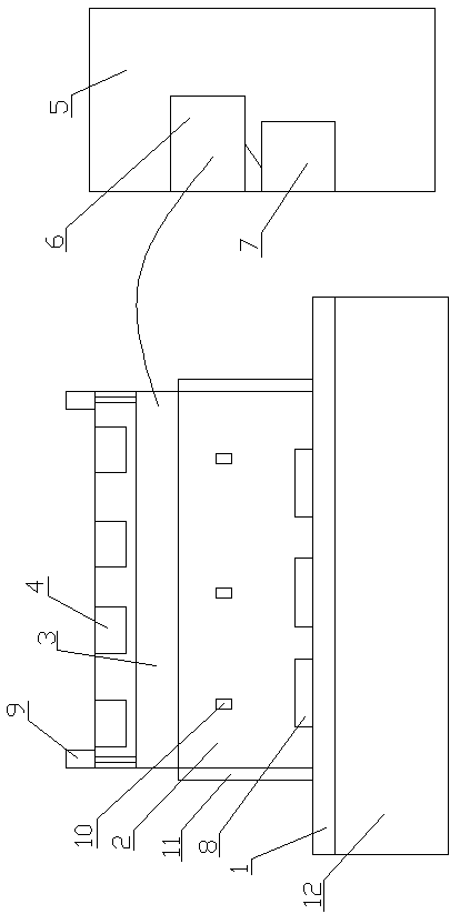
[0012] Such as figure 1 As shown, this embodiment provides a drying kiln for the surface of battery grids, which includes a conveyor belt 1 transported from right to left, a drying box 2 is arranged in the middle of the top of the conveyor belt 1, and the left and right sides of the drying box 2 have openings; A heating rod 3 is installed on the top of the box 2, and a blower 4 is distributed horizontally above the heating rod 3 in the drying box 2. The blower 4 blows downward, and the wind is heated by the heating rod 3 and blows to the conveyor belt 1; There is a control box 5, the control box 5 is provided with a power supply 6, the heating rod 3 is connected to the power supply 6, and...


PUM


Abstract

The invention aims at providing an accumulator plate grid surface drying kiln. A plate grid is put on a storage plate. The storage plate is put on a conveying belt and conveyed into a drying box. An air blower blows air to a heating rod. The air passing through the heating rod is changed into hot air. The hot air is blown to the plate grid, and thus, the plate grid is dried. A power source of theheating rod is connected with a frequency converter, and thus, the voltage and frequency of the working power source of the heating rod can be changed; and the power of the heating rod is adjusted, and thus, the temperature is adjusted. The heating rod can be ascended and descended through an ascending-and-descending motor and made to get close to the plate grid as needed, and thus, drying is accelerated. The accumulator plate grid surface drying kiln can well adapt to surface drying of the plate grid and be applicable to production.

Description

technical field [0001] The invention relates to the field of battery grid drying, in particular to a kiln for drying the surface of battery grids. Background technique [0002] The battery includes a grid, which needs to be coated during the manufacturing process, and lead paste is required for the plate, and the lead paste and paste need to be fed into the paste machine to coat the grid and paste The grid then needs to dry its surface. The surface drying device of the battery grid cannot control the temperature well, resulting in waste of energy. Therefore, it is necessary to solve this problem. Contents of the invention [0003] In order to solve the above problems, the present invention provides a kiln for drying the surface of battery grids. The grids are placed on the placement plate, and the placement plate is transported to the drying box on the conveyor belt. It turns into hot air, and the hot air is blown onto the grid to dry it. The power supply of the heating...

Claims


Application Information

Patent Timeline
Patent Type & Authority Applications(China)
IPC IPC(8): F26B15/18F26B23/06F26B21/00H01M4/21
CPCH01M4/21F26B15/18F26B21/001F26B23/06Y02E60/10
Inventor 钦晓峰陈林陆毅汪俊兵侍子强
Owner TIANNENG BATTERY WUHU
Why Eureka
Try Eureka