Check patentability & draft patents in minutes with Patsnap Eureka AI!

Manipulator inverse moving method

A mechanical arm, reverse motion technology, applied in the direction of manipulators, program-controlled manipulators, instruments, etc., can solve the problems of not being able to reach exactly, the amount of calculation is large, and the calculation results are not optimal results.

Active Publication Date: 2012-09-19
SHENZHEN BOAN INTELLIGENT CONTROL TECH CO LTD
View PDF0 Cites 0 Cited by
  • Summary
  • Abstract
  • Description
  • Claims
  • Application Information

AI Technical Summary

Problems solved by technology

However, inverse dynamics technology is often used in the study of the movement of these robotic arms, that is, the spatial coordinate point that the robotic arm needs to reach is known, so that the robotic arm can reach the target position, but in actual situations, it cannot exactly reach the target position. The target position can only reach the position closest to the target point, that is, the optimal position, which requires calculating the coordinate value of the optimal position. At present, the most commonly used method is to enumerate all possible equations for analytical equations. When the mechanical When there are many joints in the arm, the amount of calculation of these equations will become very large, resulting in very slow calculation, and the calculation result is not optimal

Method used


Image

  • Manipulator inverse moving method
  • Manipulator inverse moving method
  • Manipulator inverse moving method

Examples


Embodiment Construction

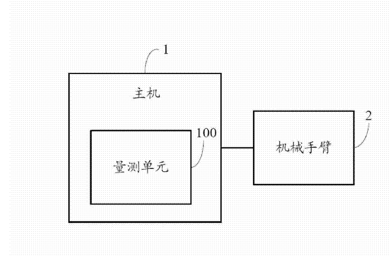
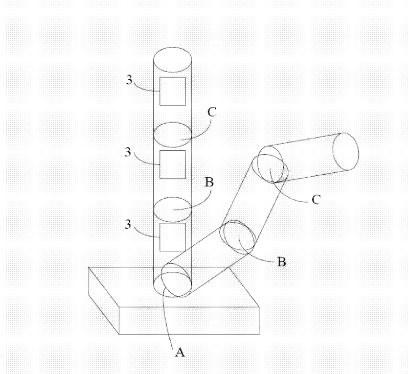
[0010] like figure 1 Shown is a hardware architecture diagram of a preferred embodiment of the method for inverse motion of the robotic arm of the present invention. The hardware architecture diagram includes a host 1 connected to a robot arm 2. In this embodiment, the robot arm 2 includes a plurality of joints. like figure 2 As shown, it is assumed that the number of joints of the mechanical arm 2 is n, and each joint includes a root node and an end node. When the joint moves, the position of the root node of the joint remains unchanged, and a motor 3 is installed in the end node. The host computer 1 sends motion instructions to the motor 3, and the motor 3 drives the end node to drive the mechanical arm 2 to move. Starting from the end of the robot arm 2 connected to the host computer 1, the joints of the robot arm 2 are named as the nth joint, respectively: the first joint, the second joint, and so on. In this figure, the root node of the first joint is A, and the end n...


PUM


Abstract

The invention relates to a manipulator inverse moving method which comprises the steps of: inputting a parameter value of a manipulator initial position and a parameter value of a target position; calculating the arrived position of a tail node of each joint after each iteration by using an iteration method according to the input parameter values of the initial position and the target position; calculating the distance between the arrived position of each iteration and the target position according to the calculated arrived position of the tail node of each joint in each iteration, and obtaining the position of each joint of the minimum distance and coordinate values of the node of each joint corresponding to the position; and driving the joint to move and arrive at the position with minimum distance with the target position by a motor on each joint.

Description

technical field [0001] The invention relates to a method for moving a mechanical arm, in particular to a method for reversely moving a mechanical arm. Background technique [0002] Precise motion control of robotic arms is very important for improving productivity and quality. Robotic arms have been widely used in industry, such as measuring arms of measuring machines, robotic arms, etc. However, inverse dynamics technology is often used in the study of the movement of these robotic arms, that is, the spatial coordinate point that the robotic arm needs to reach is known, so that the robotic arm can reach the target position, but in actual situations, it cannot exactly reach the target position. The target position can only reach the position closest to the target point, that is, the optimal position, which requires calculating the coordinate value of the optimal position. At present, the most commonly used method is to enumerate all possible equations for analytical equatio...

Claims


Application Information

Patent Timeline
Patent Type & Authority Patents(China)
IPC IPC(8): B25J9/00
CPCB25J9/1656G05B2219/40465G05B19/41
Inventor 张旨光吴新元
Owner SHENZHEN BOAN INTELLIGENT CONTROL TECH CO LTD
Features
  • R&D
  • Intellectual Property
  • Life Sciences
  • Materials
  • Tech Scout
  • Unparalleled Data Quality
  • Higher Quality Content
  • 60% Fewer Hallucinations
Learn More