Supercharge Your Innovation With Domain-Expert AI Agents!

Target seat structure

A target holder and pedestal technology, applied in the field of target holder structure, can solve the problems of discontinuous distribution of columnar target holder, uneven film thickness of plated objects, uneven distribution of atomic concentration of target materials, etc., so as to improve the uniformity, The effect of uniform target atomic concentration

Inactive Publication Date: 2010-10-27
HONG FU JIN PRECISION IND (SHENZHEN) CO LTD +1
View PDF4 Cites 4 Cited by
  • Summary
  • Abstract
  • Description
  • Claims
  • Application Information

AI Technical Summary

Problems solved by technology

[0003] However, the symmetrically arranged columnar target seats are not continuously distributed in the entire sputtering space, resulting in uneven distribution of the target atomic concentration between the columnar target seats, which may easily cause uneven film thickness of the object to be plated.

Method used


Image

  • Target seat structure
  • Target seat structure

Examples


Embodiment Construction

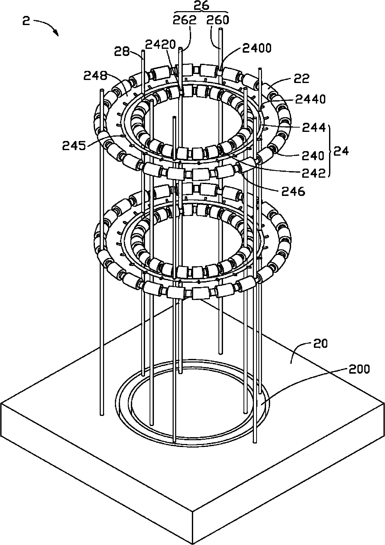
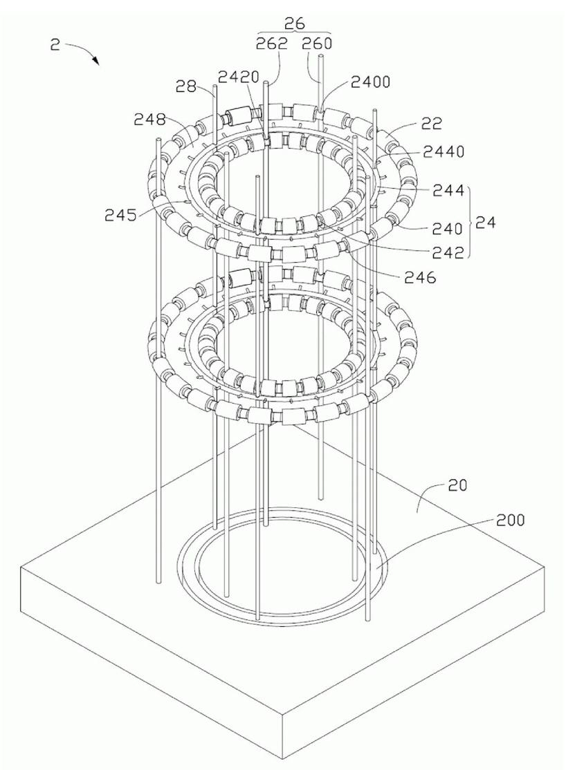
[0008] Such as figure 1 As shown, the target holder structure 2 provided by the embodiment of the present invention includes a base 20 , a target material 22 , a coating layer 24 , a target holder support 26 and a base support 28 .

[0009] The coating layer 24 includes a first target base 240 , a second target base 242 and a base 244 . The first target seat 240 , the base 244 and the second target seat 242 are concentric annular bodies with successively decreasing diameters.

[0010] The target stand support 26 can be a plurality of upright poles fixedly connected to the base 20, which includes a first target stand support 260 for supporting the first target stand 240 and a support for supporting the second target stand 242. The second target holder bracket 262 . A plurality of first connection through holes 2400 are evenly spaced on the first target base 240 , and the first target base bracket 260 passes through the first connection through holes 2400 and is fixed with the...


PUM


Abstract

The invention relates to a target seat structure which comprises a base, a target material, a coating film layer, a target seat bracket and a substrate bracket, wherein the coating film layer comprises a first target seat, a second target seat and a substrate; the first target seat, the second target seat and the substrate are respectively a homocentric annular body; the first target seat and thesecond target seat are supported on the base by the target seat bracket and enclose a continuous-closed annular coating film area in the same plane; the substrate is supported on the base by the substrate bracket and positioned in the annular coating film area; and the target material is coated on the first target seat and the second target seat. As the annular coating film area is continuously closed, target material atoms are not easy to diffuse outwards after entering into the annular coating film area in a sputtering way, the evenness of the target material atom concentration in the annular coating film area is improved.

Description

technical field [0001] The invention relates to a target seat structure. Background technique [0002] The sputtering target seat is one of the main devices in the vacuum coating equipment. Most of the existing sputtering target bases are upright columnar structures. Every two columnar target bases are arranged symmetrically with respect to the base on which the object to be plated is placed, and the surface of the opposite side of the columnar target bases is coated with a target material for coating. During coating, the target is bombarded by ionized inert gas ions, and then atoms of the target are sputtered to the area between the target seats to adhere to the surface of the object to be coated to form a film layer. [0003] However, the symmetrically arranged columnar target bases are not continuously distributed in the entire sputtering space, resulting in uneven distribution of target atomic concentration between the columnar target bases, which may easily cause unev...

Claims


Application Information

Patent Timeline
Patent Type & Authority Applications(China)
IPC IPC(8): C23C14/34C23C14/54C23C14/56
Inventor 王仲培
Owner HONG FU JIN PRECISION IND (SHENZHEN) CO LTD
Features
  • R&D
  • Intellectual Property
  • Life Sciences
  • Materials
  • Tech Scout
  • Unparalleled Data Quality
  • Higher Quality Content
  • 60% Fewer Hallucinations
Learn More