Mechatronic anti-theft lock body

An electromechanical and integrated technology, applied in the field of anti-theft lock bodies, can solve the problems of ineffective conversion between mechanical unlocking and electric unlocking, unstable operation of the motor drive mechanism, and low reliability of electromechanical integration, so as to solve the problems of ineffective conversion and anti-theft. High performance, simple structure effect

Inactive Publication Date: 2010-10-27
刘茂胜
View PDF4 Cites 17 Cited by
  • Summary
  • Abstract
  • Description
  • Claims
  • Application Information

AI Technical Summary

Problems solved by technology

The present invention can effectively solve the problem that the existing mechanical unlocking and electric unlocking cannot be effectively converted, and this is the first purpose of the present invention
[0005] The invention provides an electromechanical integrated anti-theft lock body, which can solve the problem of common electronic anti-theft locks, which have a relatively complex structure and poor strength, especially the unstable operation of the motor drive mechanism, which leads to low reliability of the electromechanical conversion. Low problem, with the help of the unique structural design of the present invention, the present invention has the effect of more convenient operation and use than the traditional mechanical lock body. Compared with other electronic lock bodies, the structure is simple, the operating mechanism is reasonable, and the strength is better. The invented motor and gear set are very stable in operation, and the reliability of electromechanical integration conversion is very high. At the same time, it can be compatible with the installation of purely mechanical lock bodies used on existing security doors. ) combined, the separate and combined use of mechanical and electronic control does not affect each other, the anti-theft performance is high, and it can be industrialized

Method used


Image

  • Mechatronic anti-theft lock body
  • Mechatronic anti-theft lock body
  • Mechatronic anti-theft lock body

Examples


Embodiment Construction

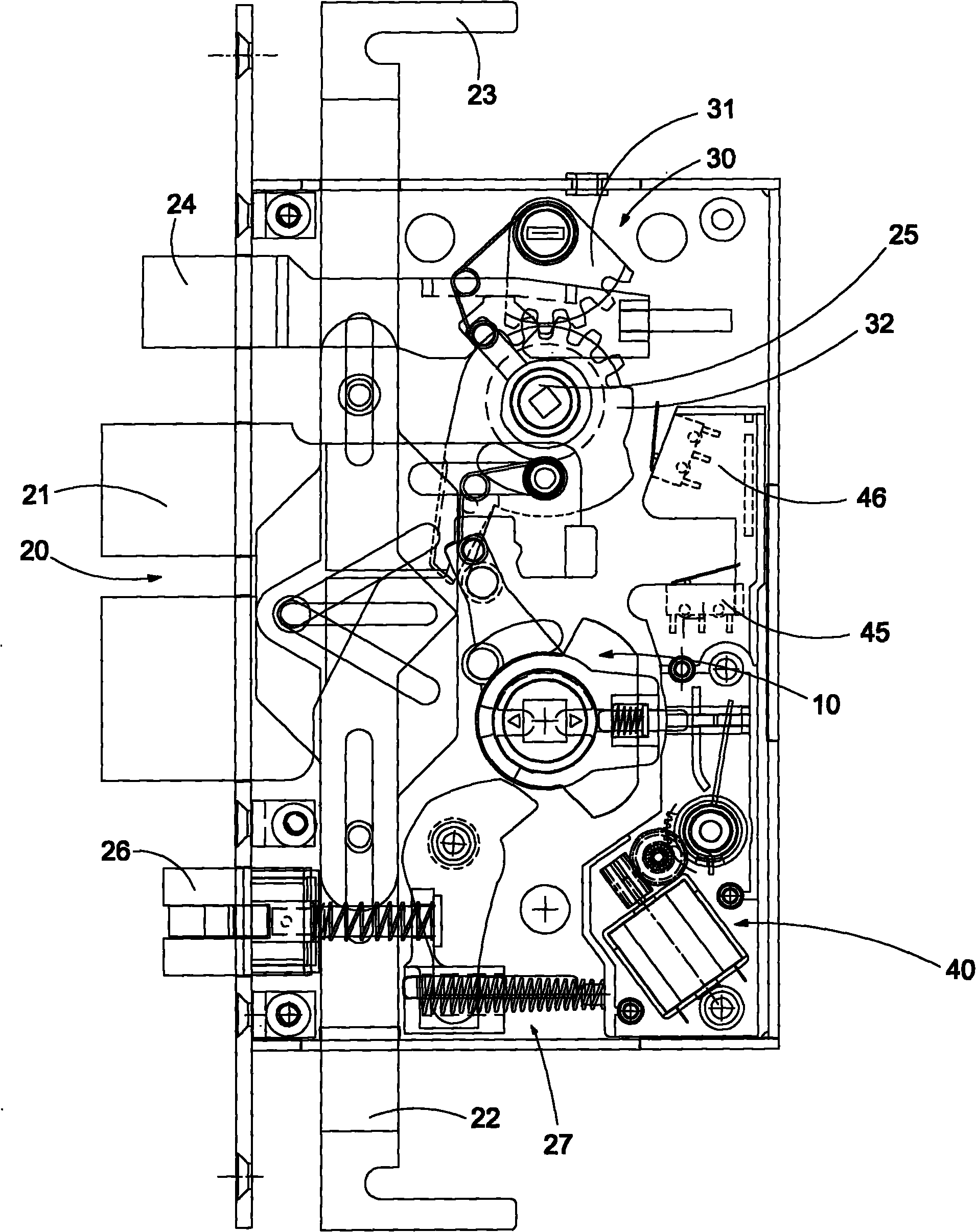
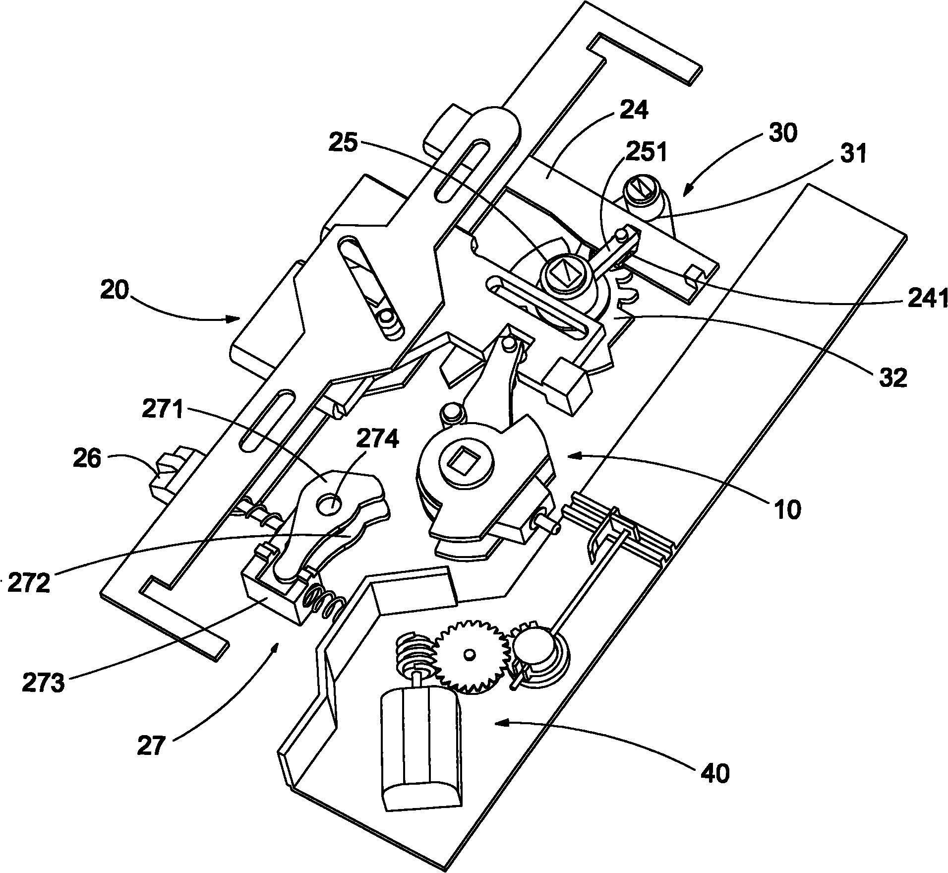
[0027] Such as Figure 1 to Figure 7 Shown is a preferred specific implementation example of the present invention, an electromechanical integrated anti-theft lock body, including a deadbolt execution unit 10, a locking unit 20, a mechanical drive unit 30 and the electric drive unit 40, wherein ,

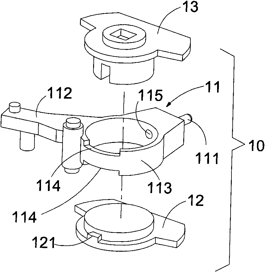
[0028] Such as image 3 , Figure 4 As shown, the deadbolt actuator unit 10 includes a toggle member 11, an inner shift fork 12 and an outer shift fork 13, wherein the inner shift fork 12 and the outer shift fork 13 are rotatably arranged on the toggle member 11 respectively. The upper and lower ends, so that when the inner shift fork 12 is rotated to the limit position, it can independently drive the toggle member 11 to rotate. The toggle member 11 is provided with a clutch pin 111, and the clutch pin 111 can be extended into when subjected to an external force. To the inside of the outer shift fork 13, the outer shift fork 13 and the shifting member 11 are fixed together.

[0...


PUM


Abstract

The invention provides a mechatronic anti-theft lock body, which comprises a bolt actuating unit, a locking unit, a mechanical drive unit and an electric drive unit. The mechanical drive unit can be driven by a mechanical key to rotate so as to drive the locking unit to unlock or lock a door lock. In the specific use, handles in and out the door can be rotated in opposite directions to drive the main bolt to extend out or retract to lock or unlock the door lock, and the motor of the electric drive unit can be started through connecting a power supply and the like, thereby realizing mechatronic switching of unlocking and locking of the door lock. The invention can effectively solve the existing problem of non-efficient switching of mechanical unlocking and electric unlocking, and can also solve the problems that the structure of the conventional electronic anti-theft lock is complex, the strength of the conventional electronic anti-theft lock is low, and particularly the motor driving mechanism can not work stably, thereby causing low reliability in mechatronic switching.

Description

technical field [0001] The present invention relates to a lockset, more specifically to a mechatronic anti-theft lock body. Background technique [0002] The current anti-theft lock body is divided into a full mechanical anti-theft lock body and an electronic intelligent anti-theft lock body. Fully mechanical anti-theft locks are less and less suitable for modern people's life characteristics due to the inconvenience of locking the door (a mechanical key is required to open or lock), and have been gradually replaced by electronic anti-theft locks. [0003] However, some existing electronic anti-theft locks are prone to the problem that the door lock cannot be opened or cannot be locked because of the defective design of the motor clutch mechanism. Some electronic anti-theft locks cause the door lock to malfunction due to the unreasonable design of the deadbolt transmission mechanism. Some can not realize the effective conversion of mechanical unblanking and electric unblan...

Claims


Application Information

Patent Timeline
Patent Type & Authority Applications(China)
IPC IPC(8): E05B47/00E05B63/14E05B15/00
Inventor 刘茂胜
Owner 刘茂胜
Why Eureka
Try Eureka