
Automatic switching dual-path transmission mechanism of punch press

A transmission mechanism and automatic switching technology, which is applied in transmission devices, mechanical equipment, belts/chains/gears, etc., can solve problems such as small step distance, low load, stamping, high speed, etc., and achieve high practical value, energy saving, The effect of increasing the strike speed

Inactive Publication Date: 2012-10-03
JINAN CASTING FORGING MACHINERY INST
View PDF1 Cites 0 Cited by
  • Summary
  • Abstract
  • Description
  • Claims
  • Application Information

AI Technical Summary

Problems solved by technology

[0003] The above-mentioned improved main transmission system has been applied to the CNC turret punch press, although through the reasonable matching of the variable connecting rod length and the small crankshaft eccentricity, it solves the two kinds of slider strokes required for mold change and stamping and The problem of optimizing the rated power of the servo motor and selecting a reasonable rated stamping frequency to meet the rated stamping torque, but when stamping with small steps and low loads, it can only provide the highest stamping speed achieved at the rated stamping frequency. This stamping speed is far away. It is far from meeting the requirements of high-speed marking and stamping with small step distance and low load

Method used


Image

  • Automatic switching dual-path transmission mechanism of punch press
  • Automatic switching dual-path transmission mechanism of punch press
  • Automatic switching dual-path transmission mechanism of punch press

Examples


Embodiment 1

[0027] Embodiment 1: A new dual-channel CNC turret punch press main drive system powered by a CNC servo motor.

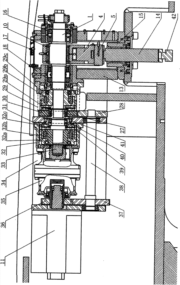
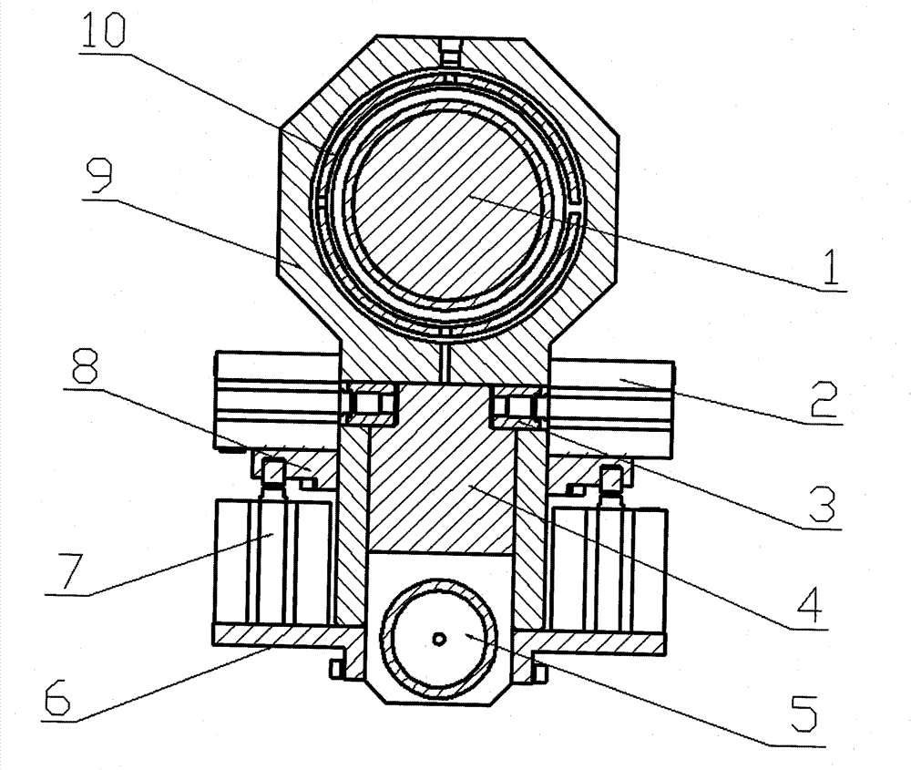
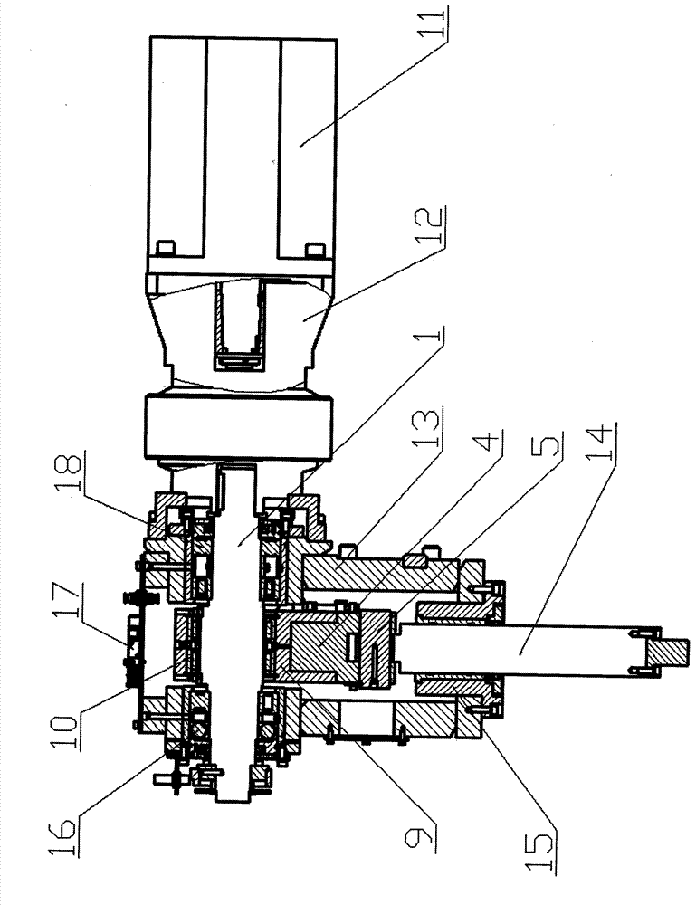
[0028] Such as figure 1 As shown, the dual-channel transmission mechanism includes two channels, straight and side, and the straight channel mainly passes through the servo motor 11-reducer 35-straight connecting shaft 33-electromagnetic tooth clutch II32-straight connecting sleeve 39-crankshaft 1-connecting rod-sliding Block 14-the transmission route of the striking head 42 realizes striking action; the bypass path mainly passes through the servo motor 11-gear II36-gear III37-bypass connection shaft 38-gear IV28-gear I30-electromagnetic tooth clutch I29-crankshaft 1-connecting rod -slider 14-strike head 42 realizes strike action.

[0029] In the straight path, the output shaft of the servo motor and the input shaft of the reducer are connected through a shaft sleeve, the output shaft of the reducer and the straight connection shaft 33 are connected through the sp...

Embodiment 2

[0041] Embodiment 2: The main transmission system of a new dual-channel CNC turret punch press powered by a CNC servo motor as the power in the bypass channel using a synchronous belt to transmit power instead of gear meshing.

[0042] The bypass path uses a synchronous belt to transmit power instead of gear meshing to transmit power. The straight path in the main transmission system and the crank-link mechanism with variable connecting rod length are the same as those in Embodiment 1. The bypass path transmission route is "servo motor 11 - synchronous pulley II-synchronous pulley III-bypass connecting shaft 38-synchronous pulley IV-synchronous pulley I-electromagnetic toothed clutch I29-crankshaft 1-connecting rod-slider 14-hitting head 42 ".

[0043] The connection method of each synchronous pulley is the same as that of the gear, that is, the output shaft of the servo motor is connected with the synchronous pulley II through the key, the synchronous pulley II and the synchro...


PUM


Abstract

The invention relates to an automatic switching dual-path transmission mechanism of a punch press. A straight-through path transmission mechanism and a bypass transmission mechanism which are fixed on a case are arranged between an output shaft and a crankshaft of a servo motor; the straight-through path transmission mechanism comprises a reducer, the reducer outputs power to the crankshaft through a straight-through path connecting shaft and a straight-through path connecting sleeve; an electromagnetic gear clutch II is arranged on the straight-through path connecting shaft and the straight-through path connecting sleeve; the bypass transmission mechanism comprises a gear II, a gear I, a gear III and a gear IV; and an electromagnetic gear clutch I is arranged between the gear I and the crankshaft. The straight-through path can meet the speed requirement in a large-load punch mode, such as quick nibbling punch, and the bypass can meet the speed requirement in a small-load punch mode, such as high-speed countermark; the rated power for driving the servo motor is only about 70 percent of the conventional rated power under the same nominal pressure; and meanwhile, the energy source is saved by about 60 percent, the noise is reduced by 10 decibels. Therefore, the automatic switching dual-path transmission mechanism of the punch press can be widely applied to numerical control punching devices.

Description

technical field [0001] The invention relates to a numerically controlled turret punch press, in particular to a new main transmission system of a numerically controlled turret punch with an automatic switching dual-path transmission mechanism and a numerically controlled servo motor as the power. Background technique [0002] The CNC turret punch press is the key equipment for sheet metal stamping. As the main transmission part of the stamping power, the mechanical design of the crank-link mechanism is traditionally used (see Figure 5 ). The crank linkage mechanism and the flywheel 21 composed of crankshaft 24 , connecting rod 25 , pin shaft 26 and slide block 23 etc. are installed on the fuselage 22 . Clutch and brake 20 are respectively connected with crankshaft 24 right side axle end and flywheel 21, and are controlled by main control valve 19 its action. During work, the main motor drives the flywheel 21 to rotate through the belt, and the power is transmitted to the c...

Claims


Application Information

Patent Timeline
Patent Type & Authority Patents(China)
IPC IPC(8): F16H37/00B21D22/02
Inventor 李兵
Owner JINAN CASTING FORGING MACHINERY INST
Learn More