
Luminance compensation method using multiwire interpolated lens

A brightness compensation and lens technology, which is applied to color TV parts, TV system parts, TVs, etc., can solve the problem of high cost of hardware memory

Inactive Publication Date: 2010-10-27
SERVICE & QUALITY TECHNOLOGY CO LTD
View PDF1 Cites 6 Cited by
  • Summary
  • Abstract
  • Description
  • Claims
  • Application Information

AI Technical Summary

Problems solved by technology

[0008] Please refer to US Patent No. 7388610 (announced on June 17, 2008) for the existing technology of using interpolation to compensate brightness. This case discloses the technology of modifying image data through extrapolation. The full-frame image is divided into 16×8 (horizontal×vertical), a total of 128 grid blocks, each grid block records the horizontal component, vertical component and diagonal component of brightness, and the gain of the first pixel in the upper left corner is used for interpolation The value is the reference, and the pixel gain value in each grid is calculated one by one by raster scanning. The calculation method is the gain value of the starting point of the grid plus the vertical component of the row, the horizontal component of the point, and the gain value of the point. Diagonal components only need addition and subtraction operations to replace the original interpolation multiplication and division operations, but the disadvantage is that the hardware memory cost is relatively high. A single color frequency takes 128 blocks as an example, which requires 128 groups of about 644bytes of memory capacity

Method used


Image

  • Luminance compensation method using multiwire interpolated lens
  • Luminance compensation method using multiwire interpolated lens
  • Luminance compensation method using multiwire interpolated lens

Examples


Embodiment 1

[0047] Embodiment 1: How polynomials describe brightness changes

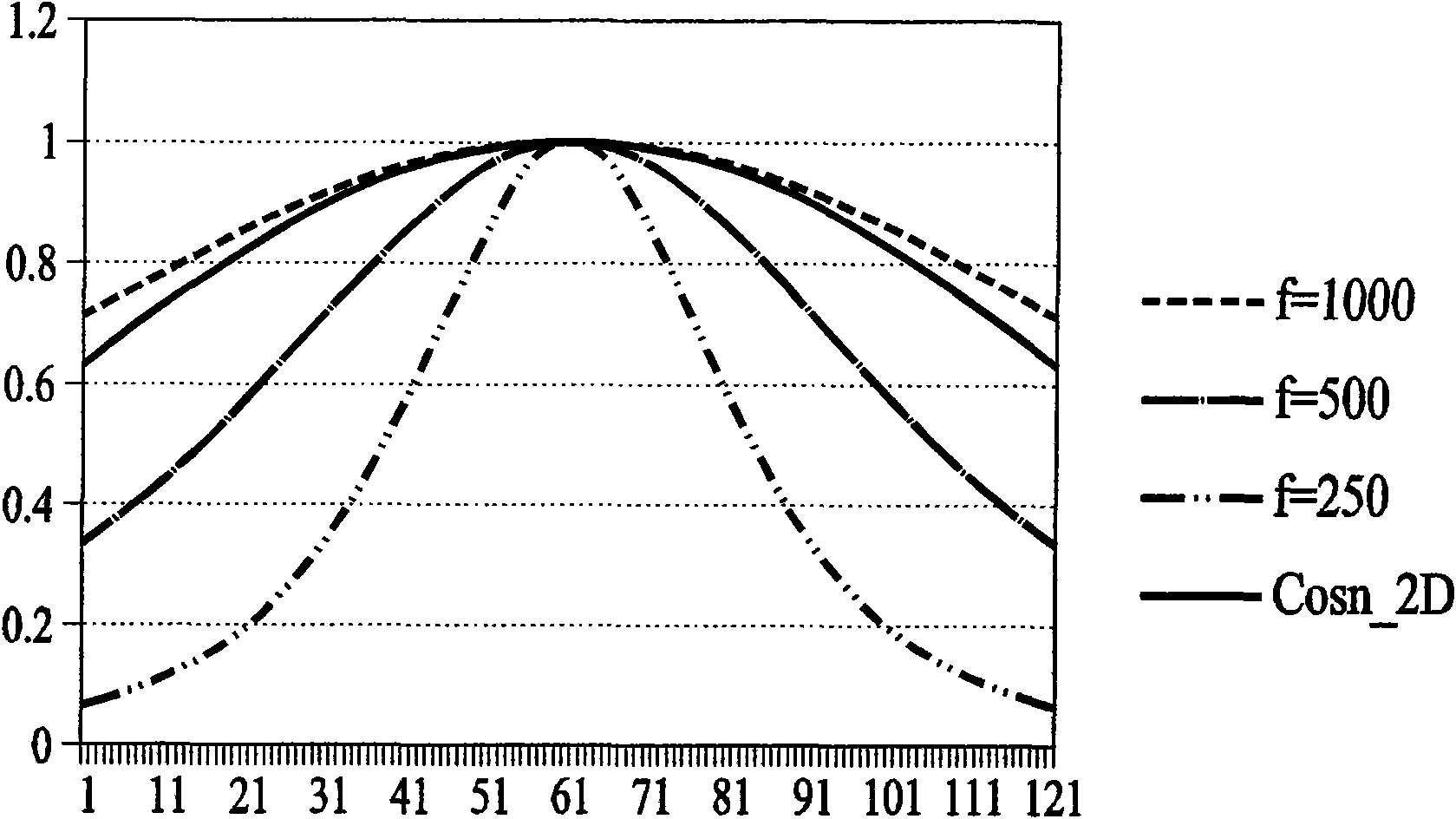
[0048] If the hardware of the lens brightness compensation method using multi-line interpolation in the present invention supports the calculation of radical operation, the radial distance from the brightness compensation target point P to the center of the mirror can be used as a variable to establish a certain direction The polynomial equation of the line is used to approximate the brightness attenuation curve in this direction, and the approach of the polynomial can be obtained by the existing complex variable regression or the Levenberg Marquardt nonlinear least square method.

[0049] The correction value of the same radius distance on the line can be obtained from the polynomial equation of the line in a certain direction The compensation value of the brightness compensation target point P (coordinates are Px, Py) is obtained by the same interpolation method:

[0050] P = ...

Embodiment 2

[0057] Embodiment 2: The implementation mode of establishing the brightness change curve by looking up the table

[0058] will be like Figure 5A The sampling points on the displayed direction line are stored in a look-up table, and the memory usage is different from that of the first embodiment, but it can describe the brightness change of the direction line in a simple and efficient way of looking up a table, and only the interpolation method is required for correction. Get the correction value for this line.

[0059] According to one of the preferred embodiments, wherein such as Figure 5A The calculation of the interpolation weight uses the distance formula from a point to a straight line, and the square of the radius distance is used to replace the square root of the original radius distance in the interpolation method, which can save the hardware circuit of the square root calculation. The calculation formula of the compensation value is as follows:

[0060] ...


PUM


Abstract

The invention discloses a luminance compensation method using a multiwire interpolated lens, which mainly utilizes multiple radial directional lines designed on a lens curved surface, arranges a plurality of equidistant or non-equidistant sampling points on line in each direction, then judges luminance compensation target point positions, utilizes gradient to calculate adjacent directional lines, calculates corrected value and interpolation weight, and utilizes interpolation to restore the whole image correction plane. In a preferable embodiment, the mode for calculating the corrected value can be that polynomial equations of two directional lines are utilized to obtain two corrected values with bi-directional on-line same radius distance, or a table lookup is utilized to obtain two corrected values of bi-directional on-line same radius position, thus the symmetrical lens compensation or non-symmetrical lens compensation is performed on the camera lens.

Description

technical field [0001] The invention discloses a lens brightness compensation method using multi-line interpolation, in particular a method for calculating correction values ​​using virtual direction line sampling points on the lens surface to restore an image plane. Background technique [0002] The camera lens is one of the most important factors affecting the quality of photos. In the camera manufacturing process, due to cost considerations, poor quality lenses may be used, and poor quality camera lenses may cause uneven imaging of light passing through the mirror. The brightness near the outside of the lens is darker than the area in the center of the lens, resulting in uncoordinated images. However, this phenomenon can be effectively improved through lens brightness correction. [0003] Currently, methods for lens brightness compensation are roughly divided into two categories: symmetrical lens compensation and asymmetric lens compensation. Among them, symmetric lens c...

Claims


Application Information

Patent Timeline
IPC IPC(8): H04N5/235
Inventor 蒋政辉谢舒菁
Owner SERVICE & QUALITY TECHNOLOGY CO LTD
Learn More