
Dialysate tank comprising a heated dialysate container, corresponding dialysis system, and method

A dialysate and container technology, applied in the field of dialysis systems, can solve problems such as poor contact between blood and one-way components, and achieve the effects of reducing safety and sanitation problems, reducing complexity, and reducing costs

Inactive Publication Date: 2010-10-27
FRESENIUS MEDICAL CARE DEUTSCHLAND GMBH
View PDF5 Cites 0 Cited by
  • Summary
  • Abstract
  • Description
  • Claims
  • Application Information

AI Technical Summary

Problems solved by technology

This will result in additional costs and unwanted contact of blood with the one-way parts

Method used


Image

  • Dialysate tank comprising a heated dialysate container, corresponding dialysis system, and method
  • Dialysate tank comprising a heated dialysate container, corresponding dialysis system, and method

Examples


Embodiment Construction

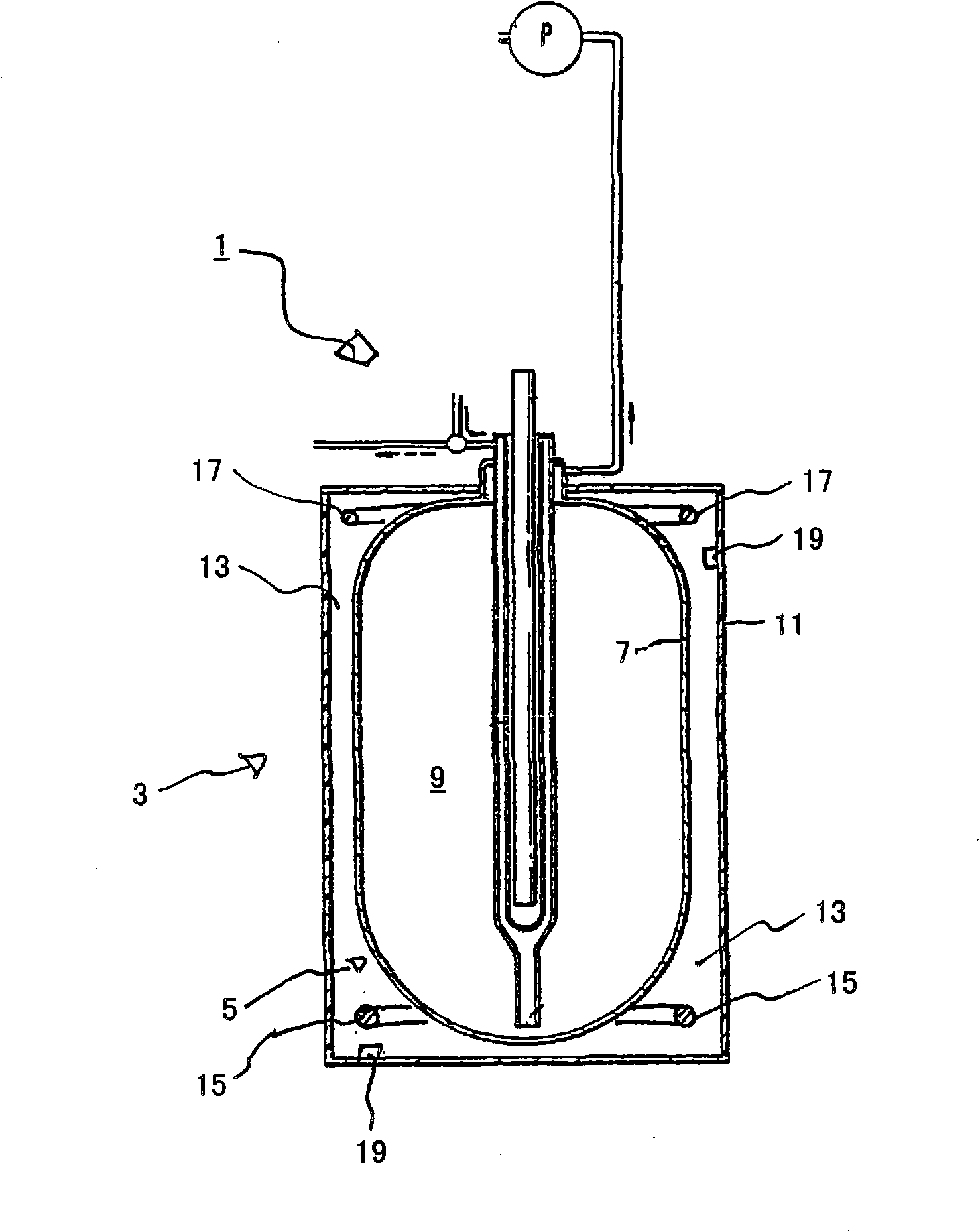
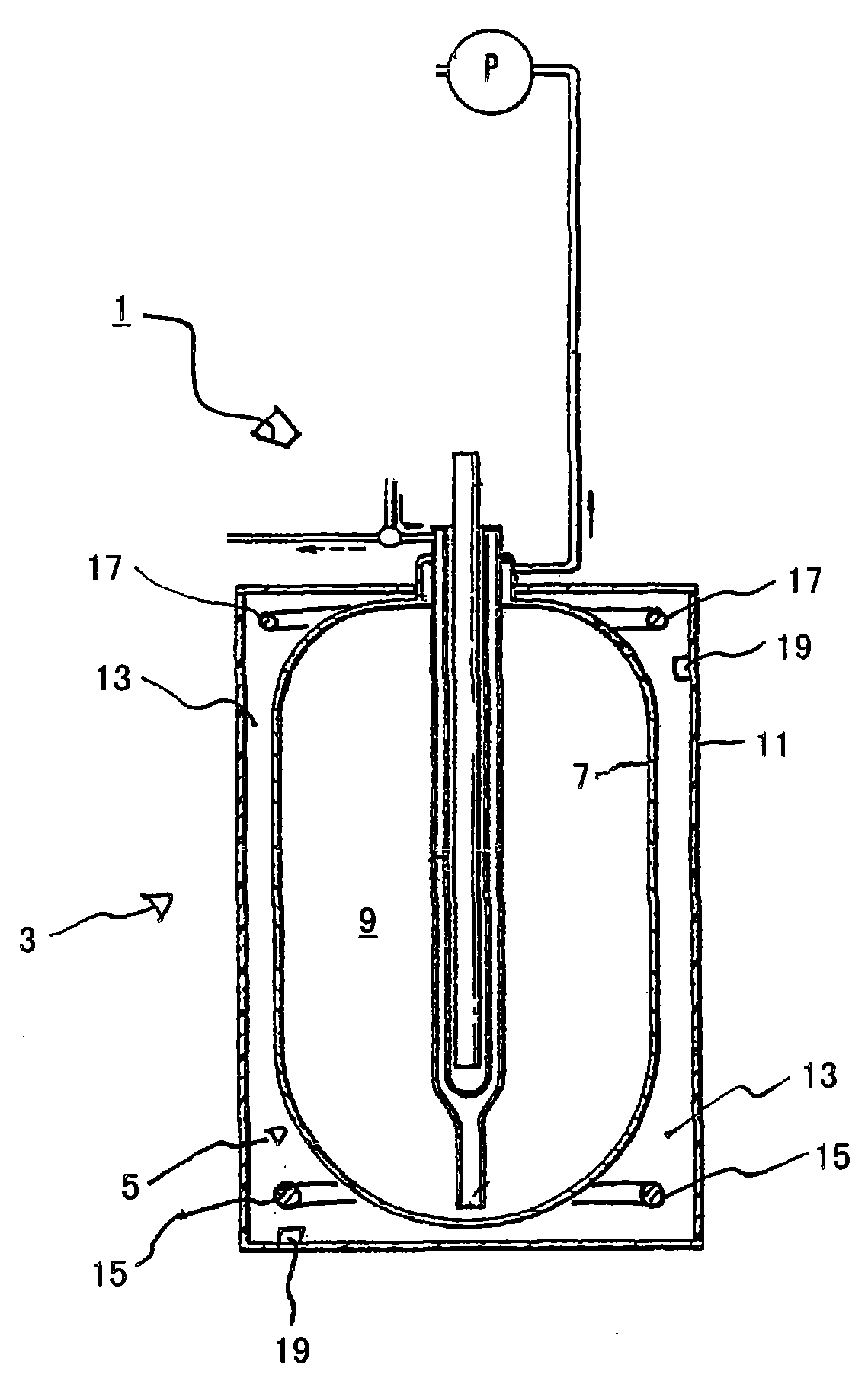
[0034] figure 1 A simplified schematic diagram showing a detail of the dialysis system 1 of the present invention. The dialysis system 1 according to the invention comprises a dialysate tank 3 . The dialysate tank comprises a dialysate container 5 with a sleeve 7 and an inner space 9 . Regardless of other design features such as figure 1 The shown dialysate container 5 can be arranged inside the dialysate tank 3 . In addition to the dialysate tank 3 , the dialysis system 1 comprises conduits arranged inside and outside the dialysate tank 3 . Catheter has nothing to do with the present invention, so in figure 1 Not marked.

[0035] The dialysate tank 3 comprises a tank body 11 as a jacket surrounding the inner space 9 . The tank body 11 is made or consists of a heat-insulating material and surrounds the dialysate container 5 with its inner space 9 and the space 13 between the dialysate container 5 and the tank body 11 .

[0036] In the bottom of the space 13 there is a hea...


PUM


Abstract

The invention relates to a device and a method for controlling, in a contactless manner, the temperature of a dialysate located in a dialysate container of a dialysate tank of a dialysis system. The invention further relates to a method for producing such a dialysate container and dialysis system according to the invention.

Description

technical field [0001] The invention relates to a dialysate tank according to the preamble of claim 1 and a dialysis system according to the preamble of claim 7 . Furthermore, it relates to a method for controlling the temperature of dialysate according to the preamble of claim 8, and a method for manufacturing a dialysate tank according to the preamble of claim 11, and a method according to the The method of manufacturing a dialysis system described in the preamble of 17. Background technique [0002] In practice, a dialysis device or system, as disclosed in the known WO 96 / 25214 patent, comprises a dialysate tank containing a dialysate container containing dialysate fluid. The dialysate (dialysate) used is usually heated to a treatment temperature and stored in a dialysate tank prior to treatment. During a patient's dialysis treatment, which typically lasts 4-5 hours, some of the cooled dialysate is not actively heated, but its cooling temperature is limited by good insu...

Claims


Application Information

Patent Timeline
Patent Type & Authority Applications(China)
IPC IPC(8): A61M1/16
CPCA61M2205/3633A61M2001/1664A61M1/1694A61M2001/166A61M1/1656A61M2205/36A61M1/166A61M1/1664A61M1/1668A61M1/1674Y10T29/49826Y10T137/0318
Inventor 马蒂亚斯·布兰德马丁·普林茨
Owner FRESENIUS MEDICAL CARE DEUTSCHLAND GMBH
Learn More