Electric connection box

A technology for electrical connection boxes, electrical parts, applied in the direction of multiple connection assemblies, electrical components, circuits or fluid lines, etc.

Inactive Publication Date: 2010-10-27
FURUKAWA ELECTRIC CO LTD +1
View PDF1 Cites 25 Cited by
  • Summary
  • Abstract
  • Description
  • Claims
  • Application Information

AI Technical Summary

Problems solved by technology

[0005] However, in the structure of Patent Document 1, due to wind pressure or vibration when the car is running, rainwater intruding from the above-mentioned gap may reach the component mounting surface of the base and wet the connection contacts of the electrical components.
Therefore, there is room for improvement from the viewpoint of reliably preventing electrical parts from malfunctioning

Method used


Image

  • Electric connection box
  • Electric connection box
  • Electric connection box

Examples


Embodiment Construction

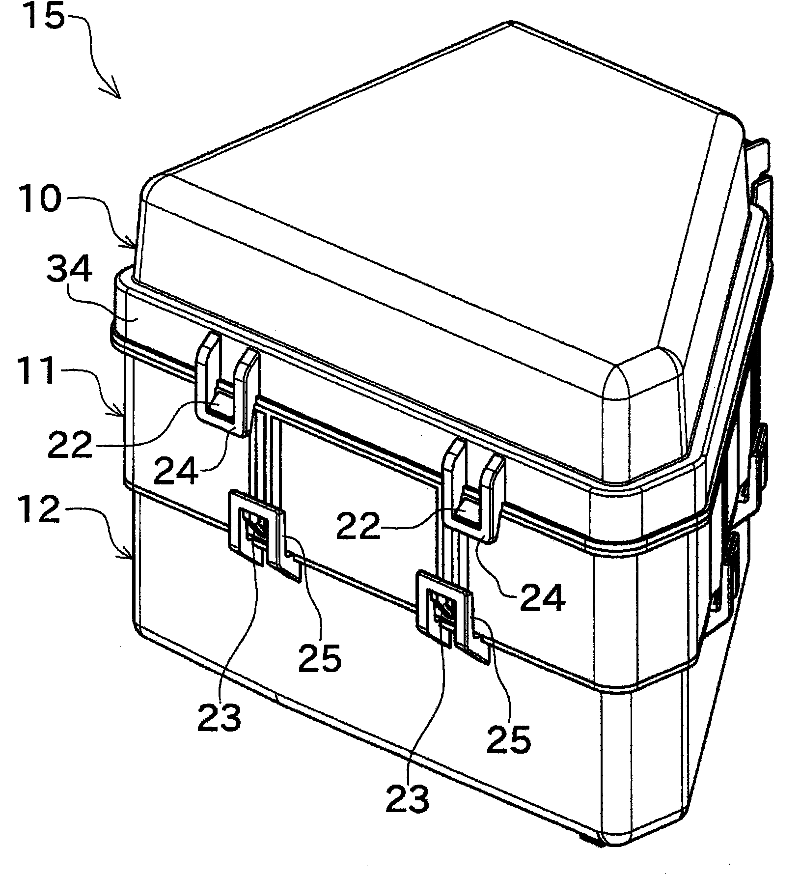
[0041] Hereinafter, preferred embodiments of the present invention will be described with reference to the drawings. figure 1 It is an external perspective view of the electrical junction box 15 which concerns on one Embodiment of this invention.

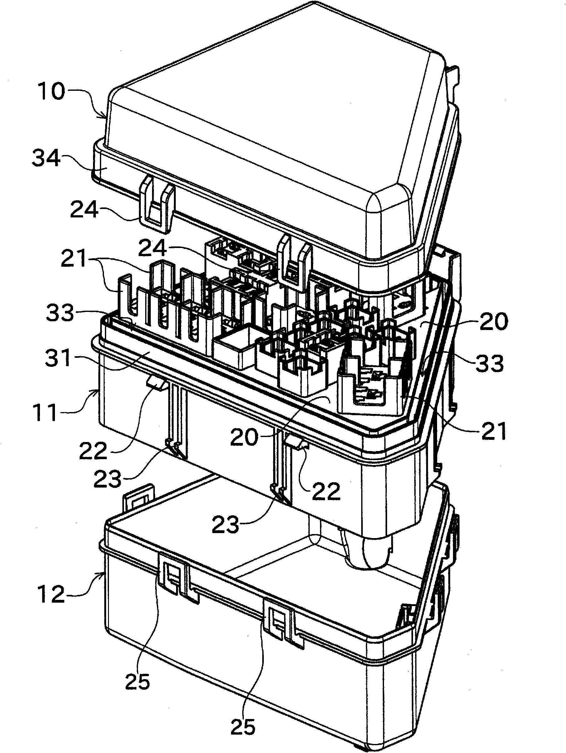
[0042] figure 1 The illustrated electrical connection box 15 is installed in the upper part of the engine room of the automobile, and includes an upper cover 10 , a base 11 , and a lower cover 12 . The above-mentioned base 11 is formed as a trapezoid in plan view.

[0043] A plurality of locking claws 22 are formed at the upper end of the peripheral portion of the base 11 , and a plurality of locking claws 23 are also formed at the lower end. On the other hand, an engaging portion 24 is formed corresponding to the locking claw 22 at the lower end of the upper cover 10 , and an engaging portion 25 is formed corresponding to the locking claw 23 at the upper end of the lower cover 12 . The upper cover 10 and the lower cover 12 are f...


PUM


Abstract

An electric connection box for an automobile effectively prevents entry of water into the box and allows water having entered the box to be easily discharged. The electric connection box has a base block (11) having a component mounting surface (20) on which an electric component such as a relay (30) is mounted, and also has an upper cover (10) for covering the electric component. The component mounting surface (20) is located above the lower end of a peripheral section (34) of the upper cover (10). On the outer periphery of the base block (11) is formed a first peripheral wall (31) fitting in the peripheral section (34) of the upper cover (10). The first peripheral wall (31) is located inside the peripheral section (34) of the upper cover (10). The upper end of the first peripheral wall (31) is located above the lower end of the peripheral section (34) of upper cover (10). The component mounting surface (20) is located above the upper end of the first peripheral wall (31).

Description

technical field [0001] The present invention relates to an electrical junction box for automobiles in which electrical components are accommodated. Background technique [0002] As an electrical junction box for automobiles arranged in an engine compartment of an automobile, an electrical junction box in which electrical components such as relays and fuses are provided on a base and covered with a top cover is known. In addition, there is also known a structure in which a wire harness connected to the above-mentioned electrical components is drawn out from the bottom of the base, and the wire harness and the like are covered with a lower cover. [0003] In such an electrical connection box, when rainwater or the like infiltrates the inside, and the water reaches the component mounting surface of the base, the connection contacts of the electrical components are wetted, causing malfunctions and the like. In order to prevent this, Patent Document 1 discloses a structure in wh...

Claims


Application Information

Patent Timeline
Patent Type & Authority Applications(China)
IPC IPC(8): H02G3/16B60R16/02H05K5/02
CPCH02G3/088B60R16/0238H05K7/026
Inventor 青木修细田径江泽树良昭
Owner FURUKAWA ELECTRIC CO LTD
Why Eureka
Try Eureka