Blanking extrusion die for soldering lug

A stamping die and blanking technology, applied in the field of blanking stamping die, can solve the problems of waste of raw materials, low stamping efficiency of the die, high production cost, etc., and achieve the effect of avoiding repeated replacement, simple operation, and improving the utilization rate and production efficiency.

Inactive Publication Date: 2010-11-03
昆山凯意工模具配套有限公司
View PDF11 Cites 9 Cited by
  • Summary
  • Abstract
  • Description
  • Claims
  • Application Information

AI Technical Summary

Problems solved by technology

[0002] Existing stamping dies, especially the punch and die of the solder tab blanking die are fixed in length and size, and a pair of dies can only punch products of one length and size. To punch products of different lengths and sizes, it is necessary to re- Make new mould, need three kinds of different lengths of 5cm, 10cm and Z0cm as a kind of solder piece, just need to make three pairs of moulds, thereby make the mould-making cost very big
[0003] Moreover, the existing product stamping method adopts a single-row stamping method. There is only one set of guide punching pins in the stamping die of the solder tab blanking die. This stamping die can only punch out one product at a time, and the stamping efficiency of the die low waste of raw materials

Method used


Image

  • Blanking extrusion die for soldering lug
  • Blanking extrusion die for soldering lug
  • Blanking extrusion die for soldering lug

Examples


Embodiment Construction

[0014] In order to make the technical means, creative features, goals and effects achieved by the present invention easy to understand, the present invention will be further described below in conjunction with specific embodiments.

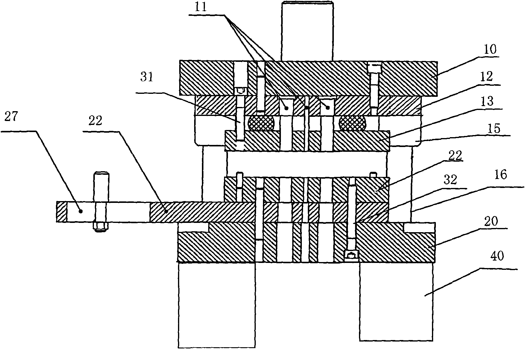
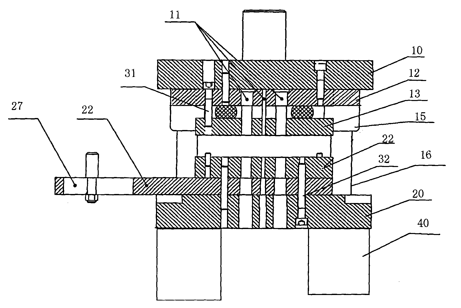
[0015] see figure 1 , the solder tab blanking stamping die of the present invention includes an upper die base 100, an upper backing plate 12, a punch 11 on the upper die base 10, a lower die base 20, a lower backing plate 22, a die 21 and a stripper plate 13; A mold foot 40 that increases the stability of mold processing is installed at the bottom of the lower mold base 20, which is convenient for users to use.

[0016] The first guide punch 31 pierced between the above-mentioned upper die base 10, the upper backing plate 12 and the stripper plate 13, the above-mentioned structure is the same as that of the existing single-branch terminal stamping die, and on the basis of the above-mentioned structure, the following Between the mold base 20, the...


PUM


Abstract

The invention discloses a blanking punch die for a soldering lug, comprising a terrace die, an upper padding plate blank, a striper plate and a concave die. The die also comprises a die pad arranged under the concave die and a second guide pin which is penetrated among a lower die base, the die pad and the striper plate, wherein at least one side of the die pad is protruded outside the concave die; an upper die base is provided with a guide sleeve and a sleeve column which are fixedly connected with the upper die base and the lower die base; the guide sleeve and the sleeve column are connected by adopting a rolling mode; and a chute is arranged on the part of the lower padding plate blank, which is protruded out from the concave die, and support parallels are arranged on the bottom of the lower die base. By mounting the second guide pin, the blanking punch die can produce two product blanking terminals in one punching stroke so as to improve the utilization ratio and production efficiency of punching plates; meanwhile, in the punching stroke, a strip plate is fed along a slide rail; after primary punching, the strip plate is moved towards one direction; and after the strip is moved for a certain distance, the strip plate is punched once again. Therefore, the punching process for a product with different lengths avoids repeatedly changing dies to ensure simple and quick operation.

Description

technical field [0001] The invention relates to a stamping die, in particular to a blanking stamping die suitable for punching solder pieces with fixed width and constant length. Background technique [0002] Existing stamping dies, especially the punch and die of the solder tab blanking die are fixed in length and size, and a pair of dies can only punch products of one length and size. To punch products of different lengths and sizes, it is necessary to re- Make new mould, need three kinds of different lengths of 5cm, 10cm and Z0cm as a kind of solder piece, just need to make three pairs of moulds, thereby make the mould-making cost very big. [0003] Moreover, the existing product stamping method adopts a single-row stamping method. There is only one set of guide punching pins in the stamping die of the solder tab blanking die. This stamping die can only punch out one product at a time, and the stamping efficiency of the die Low, waste of raw materials. Contents of the ...

Claims


Application Information

Patent Timeline
Patent Type & Authority Applications(China)
IPC IPC(8): B21D28/14
Inventor 孙新良
Owner 昆山凯意工模具配套有限公司
Why Eureka
Try Eureka