Magnetic driven walking massager

A technology of magnetic drive and massager, which is applied to equipment that compresses reflex points, magnetic therapy, showers, etc. It can solve problems such as human life, motor burnout, and easy aging, so as to save raw materials and processing costs and eliminate hidden dangers of leakage , Improve the effect of health physiotherapy

Inactive Publication Date: 2010-11-10
FUAN AOBAILI ELECTRONICS
View PDF5 Cites 4 Cited by
  • Summary
  • Abstract
  • Description
  • Claims
  • Application Information

AI Technical Summary

Problems solved by technology

But the existing massage foot tub generally all is to be directly driven by the output shaft of the motor to rotate the massage device to realize the function of massage. This massager has the following three defects: (1) because the motor and the massager must pass through The rotating shaft is directly driven, the rotating shaft is located in the water in the foot bath, and the motor is located outside the foot bath. How to completely isolate the water located in the foot bath from the motor located outside the foot bath becomes a big problem. It will lead to the serious consequences of the user's death due to electric shock; the oil seal is waterproof, because the oil seal is made of rubber material, it is easy to age, and the rolling shafts of the oil seal at both ends are prone to water leakage because the processing accuracy does not meet the requirements, resulting in electric leakage and death. (2) If the user does not use it during use, the soles of the feet exert too much pressure on the massage device, so that the massage device cannot be driven by the motor (the massage device cannot rotate), and the motor will be burned due to idling; (3) Users must also be very careful when using this massager, otherwise it is easy to cause the toes to be stuck and injured by the rotating massager

Method used


Image

  • Magnetic driven walking massager
  • Magnetic driven walking massager
  • Magnetic driven walking massager

Examples


Embodiment Construction

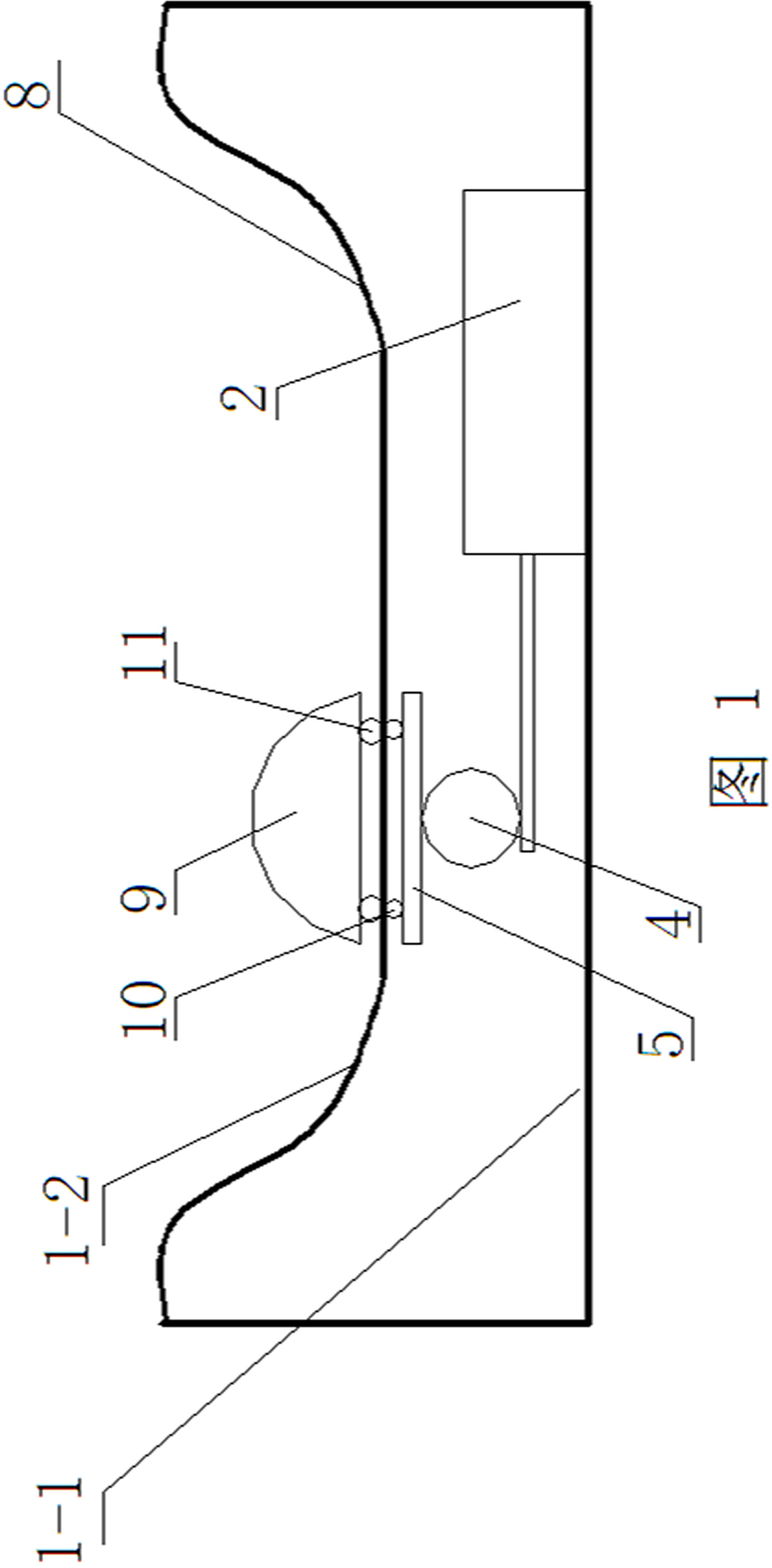
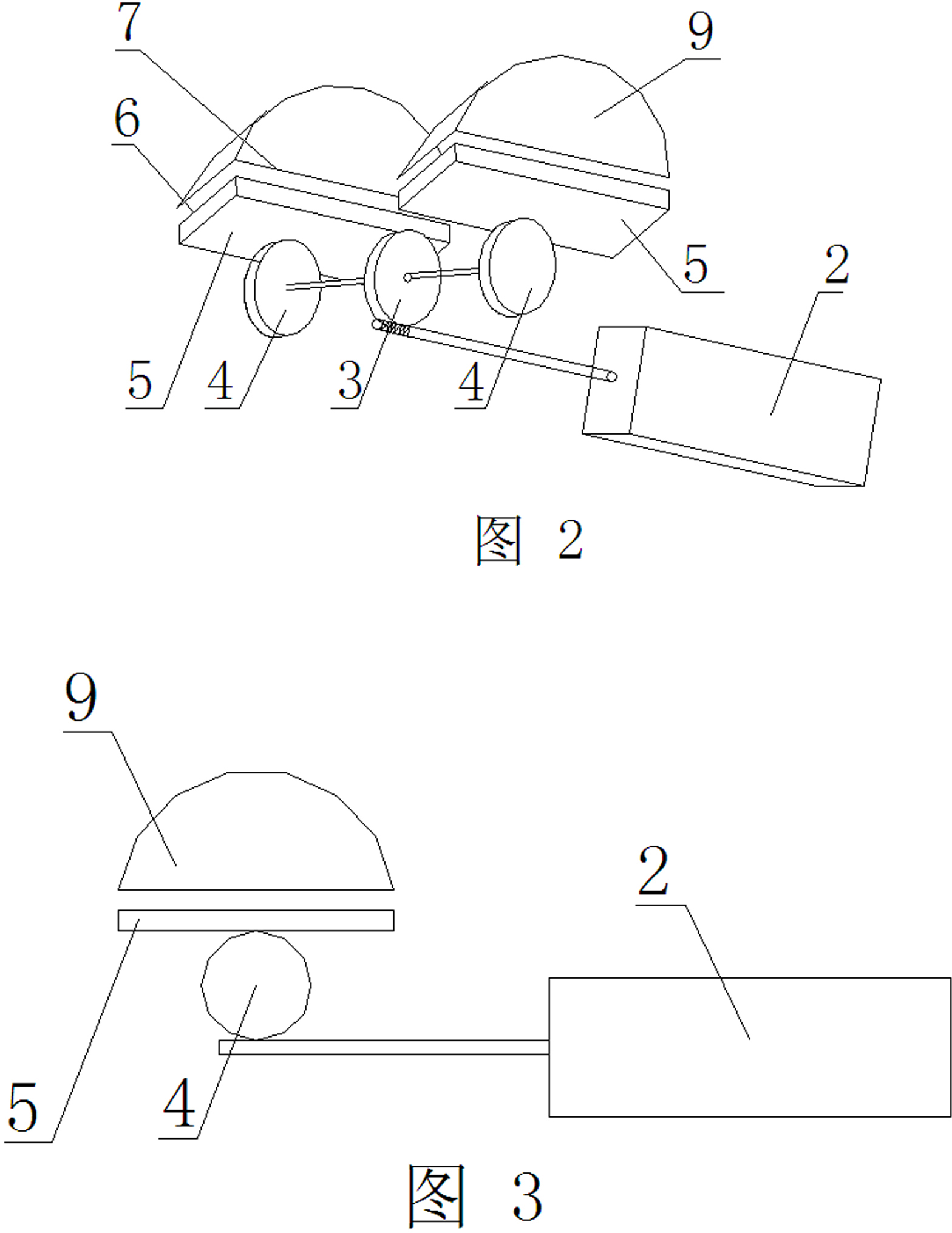
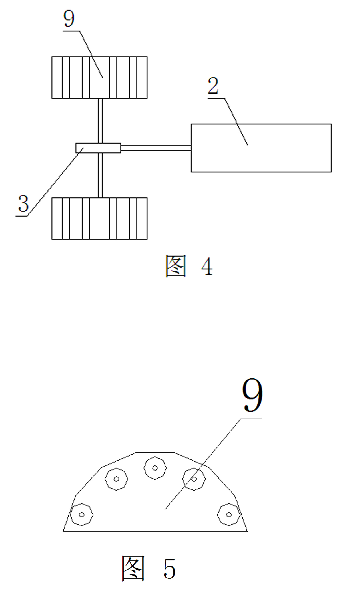
[0014] Such as figure 1 As shown, it consists of a massage device and a drive device that drives the massage device to move; the drive device includes a motor 2, a transmission device driven by the motor, and a magnetic drive device between the transmission device and the massage device; the magnetic drive The device is composed of two magnetic plates that are not connected to each other and are respectively provided with magnetic materials. One end of one magnetic plate is connected to and driven by the transmission device, and one end of the other magnetic plate is connected to the massage device and drives the massager. The device performs walking translational motion.

[0015] Opposite surfaces are provided on the two magnetic plates, and magnetic materials with alternately distributed N poles and S poles are provided on the opposite surfaces. The transmission device includes a motor output shaft with a worm, a worm gear 3 meshing with the motor output shaft, a gear 4 coa...


PUM


Abstract

The invention provides a magnetic driven walking massager with simple structure, safety and reliability. The magnetic driven walking massager comprises a massaging device and a driving device for driving the massing device to move, the driving device comprises a motor, a transmission device driven by the motor, and a magnetic driving device arranged between the transmission device and the massaging device; the magnetic driving device is formed by two magnetic boards which are not mutually connected and respectively provided with a magnetic material, one end of the one magnetic board is connected with the transmission device which drives the magnetic board, and one end of the other magnetic board is connected with the massaging device which is driven by the magnetic board to do walking and translational motion. The invention has the advantages that due to the adoption of a novel driving mode combining motor driving and magnetic material driving, the motions inside and outside a foot bath basin can be realized without mutually connected driving shafts, thus the water bath inside the foot bath basin is completely isolated with the motor outside the foot bath basin, thereby putting and end to the hidden danger of electric leakage.

Description

technical field [0001] The invention relates to a walking massager with magnetic drive. Background technique [0002] Because there are a large number of acupuncture points distributed on the two insteps or soles of the human body, with the improvement of people's living standards, foot washing is no longer simply for cleaning the dirt on the feet, but has become a tool for people to keep fit. A method and a means. But the existing massage foot tub generally all is to directly drive the massage device to rotate by the output shaft of the motor to realize the function of massage. This massager has the following three defects: (1) because the motor and the massager must pass through The rotating shaft is directly driven, the rotating shaft is located in the water in the foot bath, and the motor is located outside the foot bath. How to completely isolate the water located in the foot bath from the motor located outside the foot bath becomes a big problem. It will lead to the...

Claims


Application Information

Patent Timeline
IPC IPC(8): A61H39/04A61N2/08A47K3/022
Inventor 林学金
Owner FUAN AOBAILI ELECTRONICS
Why Eureka
Try Eureka