Perforating die for door guide rail

A technology for punching dies and door guide rails, applied in the field of stamping dies, can solve the problems of increased enterprise costs, low processing efficiency, and poor processing effects, and achieve the effects of eliminating hidden dangers of missed punching, improving work efficiency, and simple structure

Inactive Publication Date: 2016-01-06
丹阳市吉茂机械工具厂
View PDF7 Cites 4 Cited by
  • Summary
  • Abstract
  • Description
  • Claims
  • Application Information

AI Technical Summary

Problems solved by technology

[0002] At present, the installation holes of the door guide rails are single punched by a punching machine, which has low processing efficiency, increases the cost of the enterprise, has high labor intensity, and has great potential safety hazards, especially the processing effect is poor.

Method used


Image

  • Perforating die for door guide rail
  • Perforating die for door guide rail
  • Perforating die for door guide rail

Examples


specific Embodiment approach

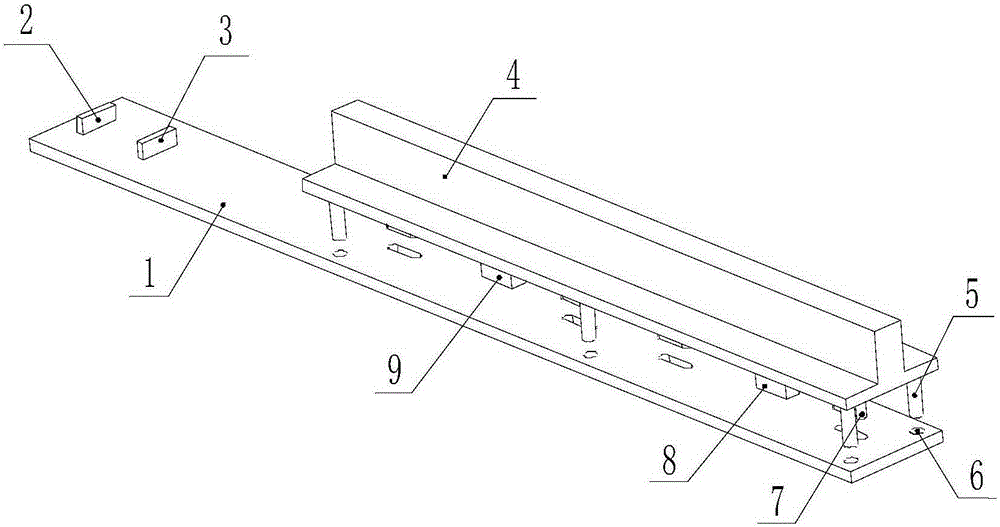
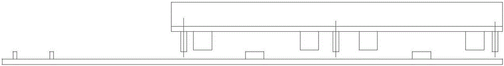
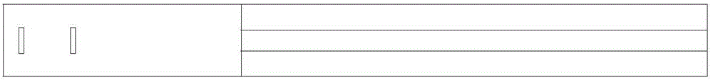
[0017] Examples such as figure 1 , figure 2 , image 3 with Figure 4 As shown, a door guide rail punching die includes a lower die, a fixed backer, a movable backer, an upper die, a guide column, a guide hole, a stamping head, a left limit boss and a right limit boss; A fixed backer and a movable backer are installed on the surface near the left side. The movable backer is located on the right side of the fixed backer. The lower mold is provided with three sets of guide holes, each with two guide holes. The left limit The boss and the right limit boss are fixedly installed on the top surface of the lower die, and the bottom surface of the upper die is provided with three guide posts, and each group is provided with two guide posts, and the guide posts on the upper die are located on the lower die. Directly above the guide hole, four stamping heads are installed on the bottom surface of the upper die.

[0018] Preferably, both the fixed backing and the movable backing are...


PUM


Abstract

The invention discloses a perforating die for a door guide rail. The perforating die mainly comprises a lower die body, a fixed backer, a movable backer, an upper die body, guide posts, guide holes, punching heads, a left limiting boss and a right limiting boss. The fixed backer and the movable backer are mounted on the top face of the lower die body and close to the left side face. The movable backer is located on the right side of the fixed backer. The three sets of guide holes are formed in the lower die body. Each set of guide holes comprises two guide holes. The left limiting boss and the right limiting boss are fixedly mounted on the top face of the lower die body. The three sets of guide posts are arranged on the bottom face of the upper die body. Each set of guide posts comprises two guide posts. The guide posts on the upper die body are located over the guide holes in the lower die body. The four punching heads are mounted on the bottom face of the upper die body.

Description

technical field [0001] The invention relates to the technical field of stamping dies, in particular to a door guide rail punching die. Background technique [0002] At present, the mounting holes of the door guide rails are single punched by a punching machine, which has low processing efficiency, increases the cost of the enterprise, has high labor intensity, and has great potential safety hazards, especially the processing effect is poor. Contents of the invention [0003] The technical problem to be solved by the present invention is to provide a door guide rail punching die with a simple structure and low cost, which improves work efficiency and eliminates the hidden danger of missed punching through integral punching by a bending machine. [0004] The technical solution adopted by the present invention to solve the technical problem is: a door guide rail punching die, including a lower die, a fixed backer, a movable backer, an upper die, a guide column, a guide hole, ...

Claims


Application Information

Patent Timeline
Patent Type & Authority Applications(China)
IPC IPC(8): B21D28/34
Inventor 唐国华袁军峰
Owner 丹阳市吉茂机械工具厂
Why Eureka
Try Eureka