
Golf club head

A golf club head and golf club technology, applied in golf balls, golf clubs, sports accessories, etc., can solve problems such as disadvantages and affecting the quality characteristics of the club head.

Active Publication Date: 2010-11-10
ROGER CLEVELAND GOLF
View PDF7 Cites 2 Cited by
  • Summary
  • Abstract
  • Description
  • Claims
  • Application Information

AI Technical Summary

Problems solved by technology

However, this geometrical constraint can adversely affect the quality characteristics of one or more club heads within the set

Method used


Image

  • Golf club head
  • Golf club head
  • Golf club head

Examples


Embodiment Construction

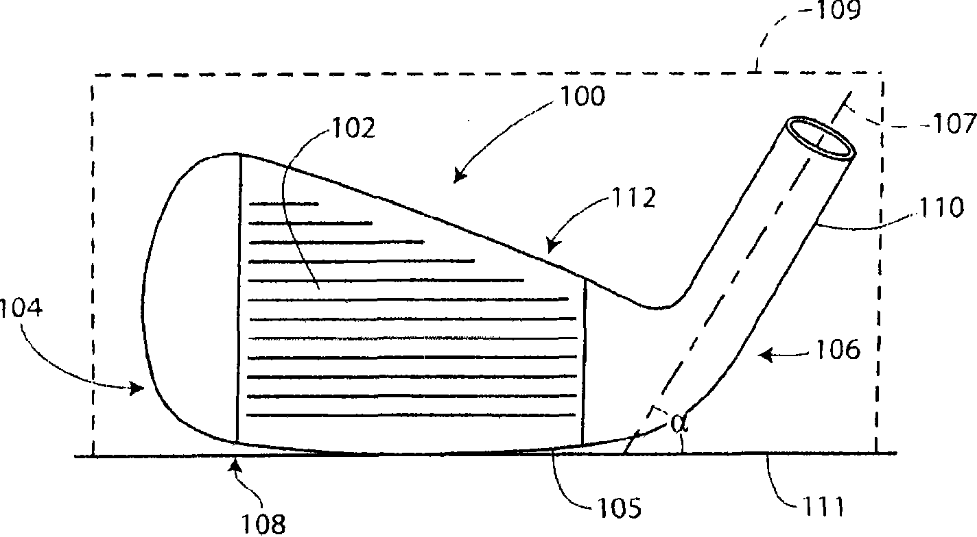
[0028] refer to Figure 1A A golf club head 100 according to one or more aspects of this invention may generally include a toe 104, a heel 106, a sole 108, a top 112, a ball striking face 102 with a leading edge 105, and a club receiving (not shown). out) socket 110 for use. The socket 110 has a socket centerline 107 . The ball striking face 102 may be integral with the club head, or may be attached to the club head, such as by welding, brazing, adhesive bonding, or mechanical interlocking.

[0029] Unless otherwise stated, all parameters described below are specified with club head 100 in a "reference position." As used herein, a "reference position" refers to a position of club head 100 in which socket centerline 107 lies within imaginary vertical plane 109 and is oriented at an actual angle α relative to ground plane 111 . Plane 109 is oriented generally parallel to leading edge 105 .

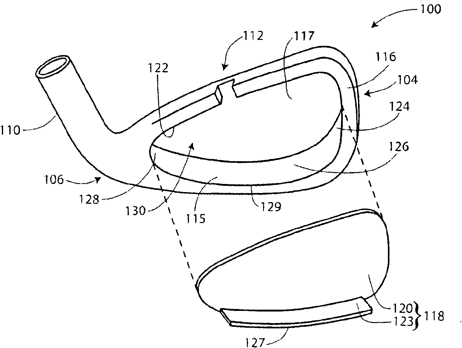
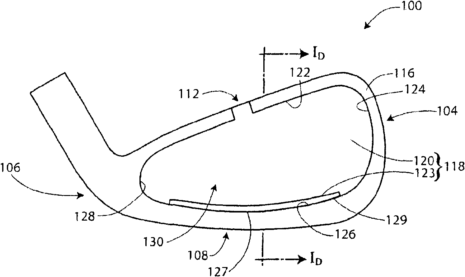
[0030] like Figure 1B As shown, golf club head 100 may also include a rear pocket 1...


PUM


Abstract

At least two golf clubs of a set, according to one or more aspects of the present invention, may include a strike face and a perimeter weighting element disposed behind the strike face. The perimeter weighting element may include an inner peripheral wall having a sole surface, a top surface, a heel surface, and a toe surface. A cavity, having a base surface, may be delimited by the inner peripheral wall and may include an insert disposed therein. The insert may comprise a primary element passively flexurally associated with one or more secondary elements and may be substantially identical for each head within the set. The primary element may be associated with the base surface and the at least one secondary element may be associated with at least one of the sole surface, the top surface, the toe surface, and the heel surface.

Description

Background technique [0001] Iron-type golf club heads can generally be categorized as "blade-type" and "perimeter-weighted". Perimeter-weighted iron-type golf club heads may have a substantial concentrated mass, sometimes referred to as a perimeter weighting element, in the form of at least one perimeter wall distributed behind the ball striking face. Perimeter weighted iron-type golf clubs may also be referred to as "cavity back" irons because the perimeter weighting elements typically define a pocket at the rear of the golf club head opposite the ball striking face. [0002] In order to improve the tactile feedback conveyed to the golfer when the ball is struck, at least a portion of the recess and the peripheral weighting element at the rear of each cavity back set may be provided with one or more vibration dampening members to reduce undesired Ideal for dynamic incentives (synonymous with mishit). Those skilled in the art will recognize that the usual progression of club...

Claims


Application Information

Patent Timeline
Patent Type & Authority Applications(China)
IPC IPC(8): A63B53/04
CPCA63B53/047A63B2209/00
Inventor S·J·帕克K·R·塔斯特罗R·范德亥登
Owner ROGER CLEVELAND GOLF
Learn More