
Method and apparatus for improving gimbal stability

Active Publication Date: 2015-03-05
BAE SYST INFORMATION & ELECTRONICS SYST INTERGRATION INC
View PDF10 Cites 8 Cited by
  • Summary
  • Abstract
  • Description
  • Claims
  • Application Information

AI Technical Summary

Benefits of technology

The invention is a new system for stabilizing infrared countermeasure systems. It uses two small and lightweight rate sensors placed at the gimbal pointing mirrors to directly sense and measure any unwanted movement. This eliminates the need for gyro stabilization and reduces the noise introduced by motor-driven elements. The system also uses a mechanical stabilization system to cancel out the angular errors caused by aircraft motion. The use of single axis rate sensors and their alignment with the elevation and azimuth axes of the gimbal results in enhanced stability and the elimination of tonal noise. The system also allows for a more advantageous mass distribution of the elevation gimbal assembly.

Problems solved by technology

Note that these rate sensors are very small and lightweight and involve piezoelectric devices, as opposed to rotating gyro discs.
These gyroscopic units are exceedingly heavy and cannot easily be supported by optical elements in a DIRCM head.
Moreover, it is virtually impossible to provide balancing when providing gyroscopes at the extremities of a two axis gimbaling system.

Method used


Image

  • Method and apparatus for improving gimbal stability
  • Method and apparatus for improving gimbal stability
  • Method and apparatus for improving gimbal stability

Examples


Embodiment Construction

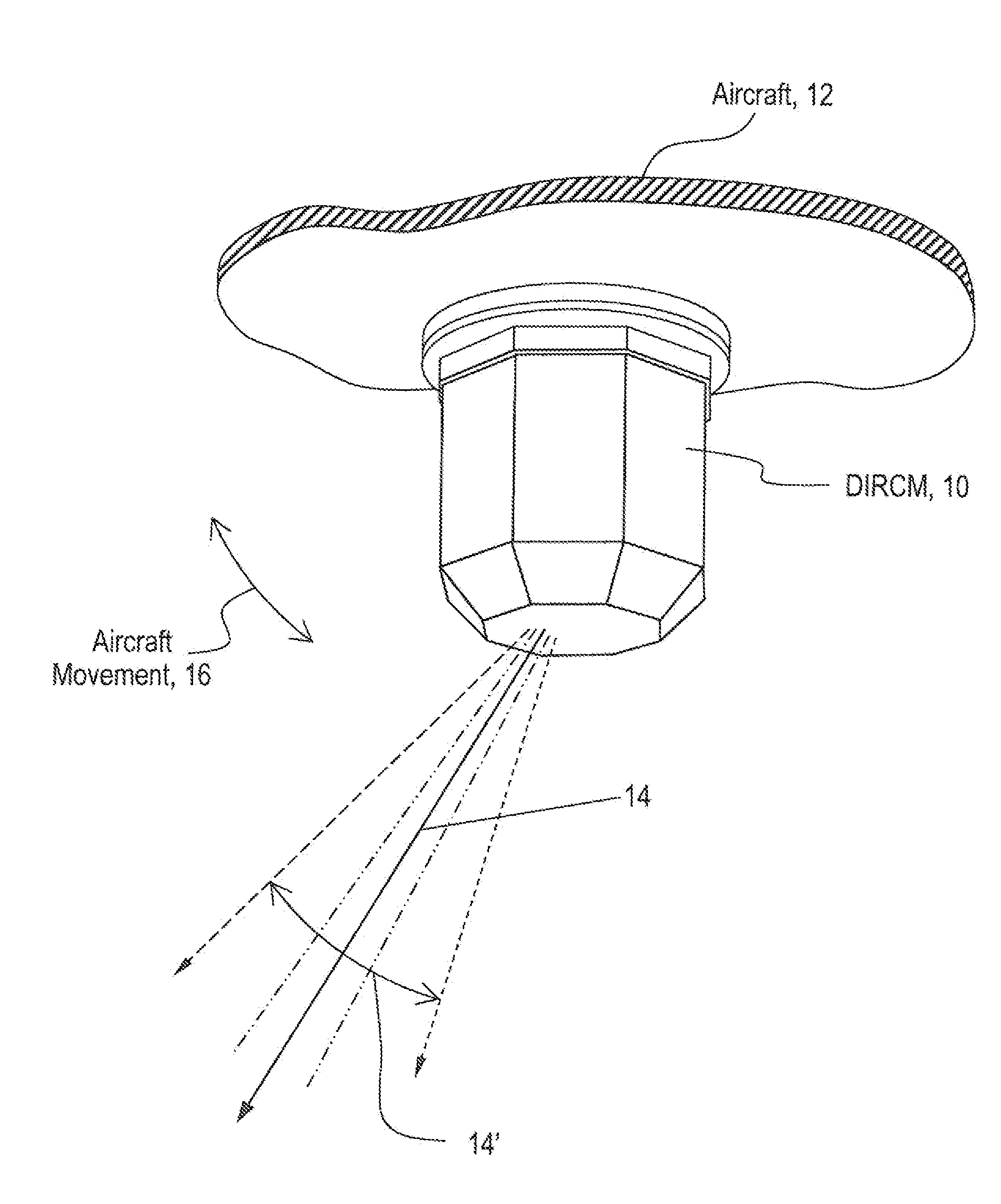
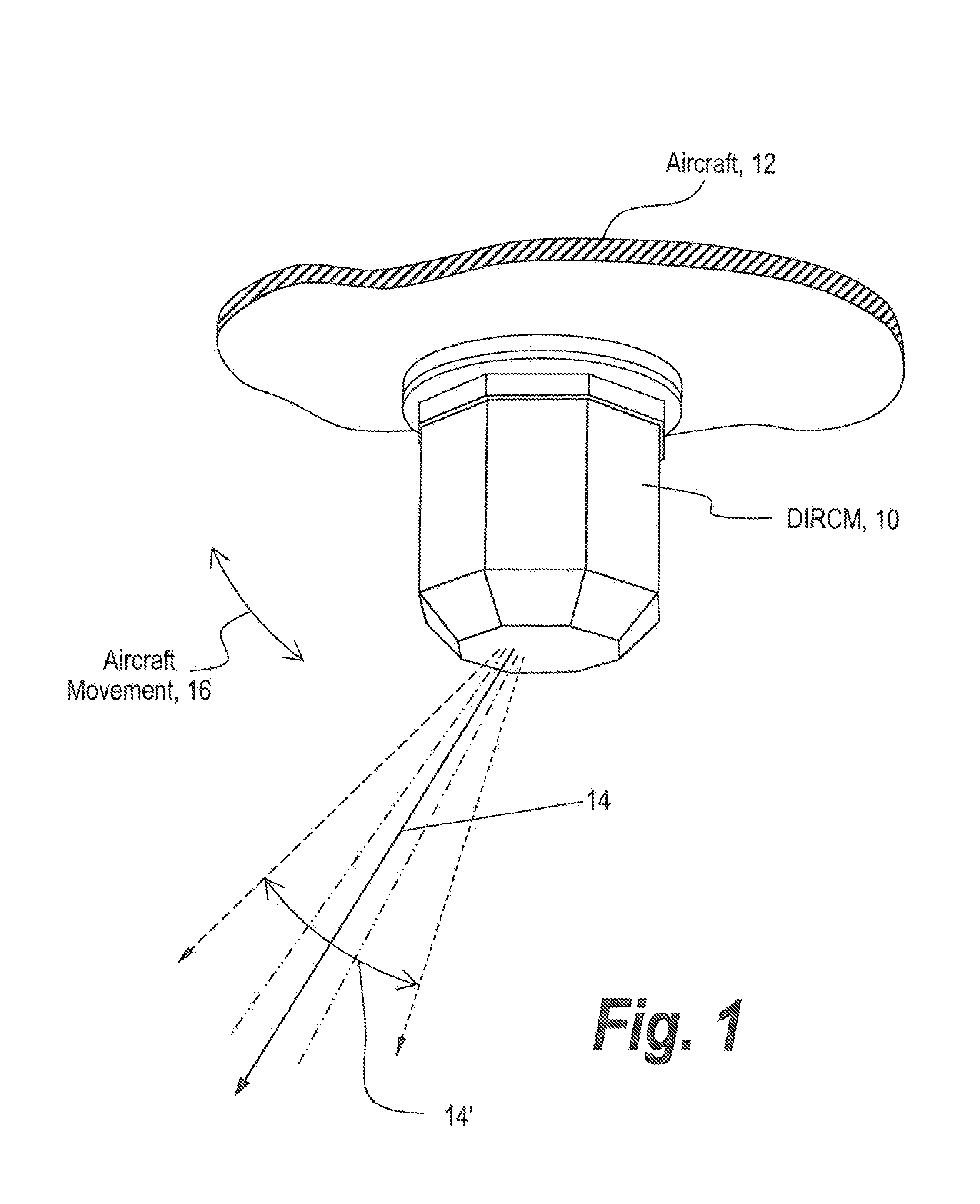
[0028]Referring now to FIG. 1, a DIRCM or directed infrared countermeasure gimbal 10 is mounted to an aircraft fuselage 12 from which laser beams 14 emanate in the directions indicated.

[0029]It will be appreciated that if the aircraft yaws, rolls or pitches during the time that the gimbal-carried internal camera in the directed infrared countermeasure system is off during an integration interval then the pointing direction will exhibit significant aiming point errors depending on aircraft movement 16 as illustrated by beam divergence 14′.

[0030]While aim-point errors may be eliminated by gyro stabilization of gimbal 10, as mentioned above, these types of systems have significant disadvantages.

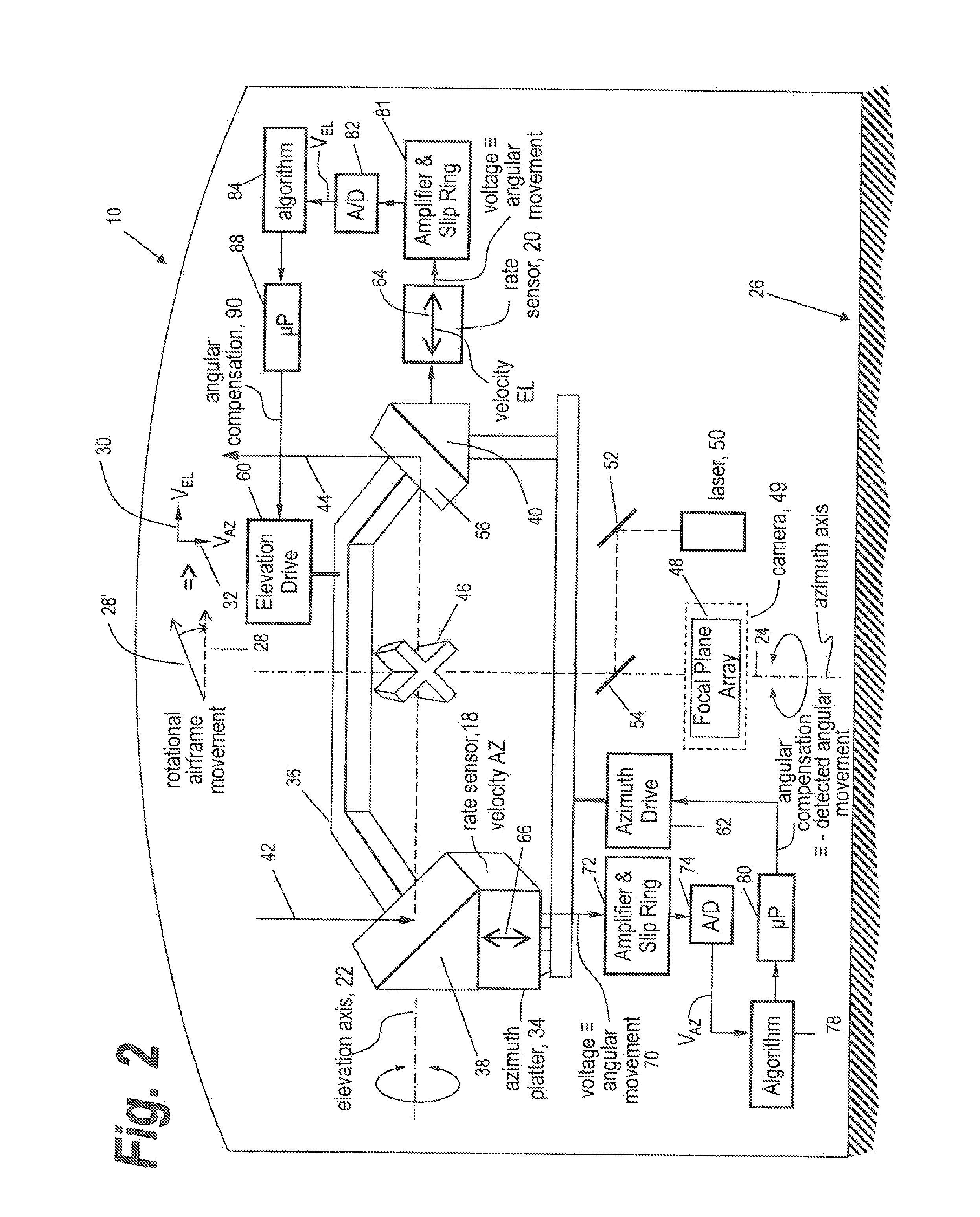
[0031]Referring now to FIG. 2, what is shown for gimbal 10 is the utilization of single orthogonal rate sensors 18 and 20 aligned respectively along an elevation axis 22 and parallel to an azimuth axis 24 to be able to sense gimbal platform 26 movement in two orthogonal directions; and specifica...


PUM


Abstract

Enhanced stability for infrared countermeasure systems is provided by using a pair of single axis rate sensors having orthogonal active axes, preferably aligned with the elevation axis and the azimuth axis of the gimbal. The outputs of the orthogonal single axis rate sensors are used to detect instantaneous aircraft angular movement and to use the detected movement to drive the elevation and azimuth motors of the gimbal to move the output mirror for the gimbal to cancel the detected movement.

Description

RELATED APPLICATIONS[0001]This application is a continuation of U.S. application Ser. No. 12 / 460,014 filed Jul. 9, 2009 and claims rights under 35 USC §119(e) from U.S. Application Ser. No. 61 / 134,464 filed Jul. 9, 2008, the contents of which are incorporated herein by reference.FIELD OF THE INVENTION[0002]This invention relates to directed infrared countermeasure, DIRCM, systems for the protection of aircraft from infrared seeking guided missiles and more particularly to a method and apparatus for improving gimbal stability utilizing single axis rate sensors.BACKGROUND OF THE INVENTION[0003]When utilizing directed infrared countermeasure (DIRCM) systems, the systems employ a gimbal pointing system which is used in the tracking and lazing of a target once it has been detected. The gimbal tracking is provided by a DIRCM gimbal head that has pointing mirrors and an embedded IR camera. The camera has a frame rate and integrates the collected data during which the camera is temporarily ...

Claims


Application Information

Patent Timeline
IPC IPC(8): G05D3/14F41H13/00
CPCF41H13/0056G05D3/14F41G7/224F41H13/0062G01S7/495G05B19/042G05B2219/41116
Inventor CORELLA, ARMANDO
Owner BAE SYST INFORMATION & ELECTRONICS SYST INTERGRATION INC
Learn More