
Actuating tool bar

A tool and bar technology, which is applied in the field of weaving tool bar, can solve the problems of limiting the working speed of weaving tool bar, and achieve the effect of favorable mass distribution, favorable moment of inertia, and expanded possibilities

Inactive Publication Date: 2013-03-27
KARL MAYER TEXTILMASCHFAB GMBH
View PDF5 Cites 6 Cited by
  • Summary
  • Abstract
  • Description
  • Claims
  • Application Information

AI Technical Summary

Problems solved by technology

This limits the working speed of the braiding tool bars

Method used


Image

  • Actuating tool bar
  • Actuating tool bar
  • Actuating tool bar

Examples


Embodiment Construction

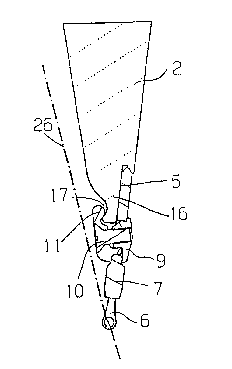
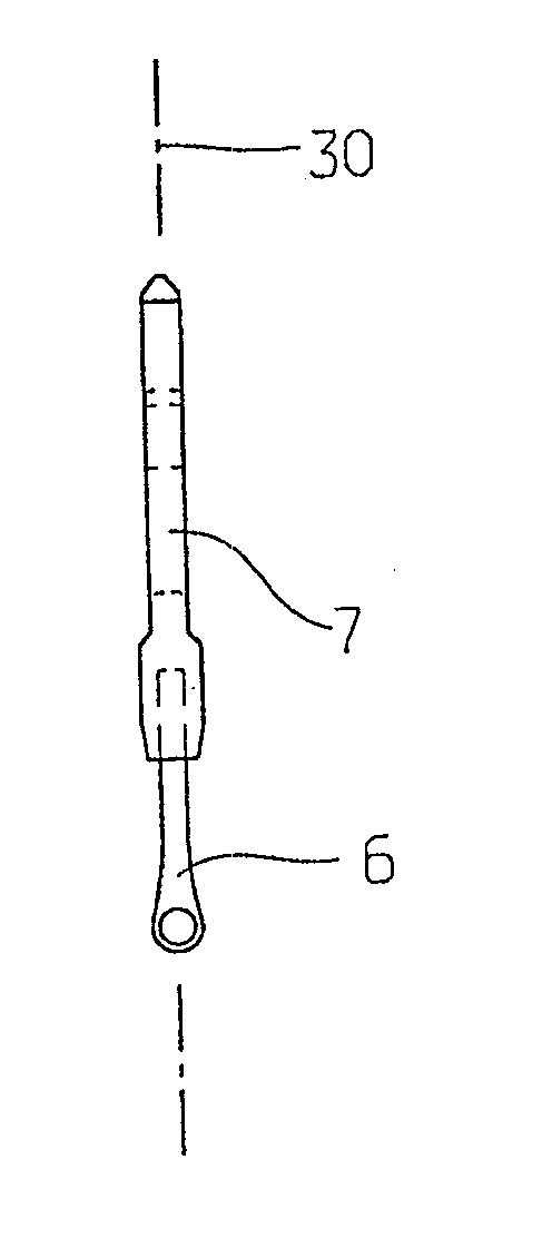
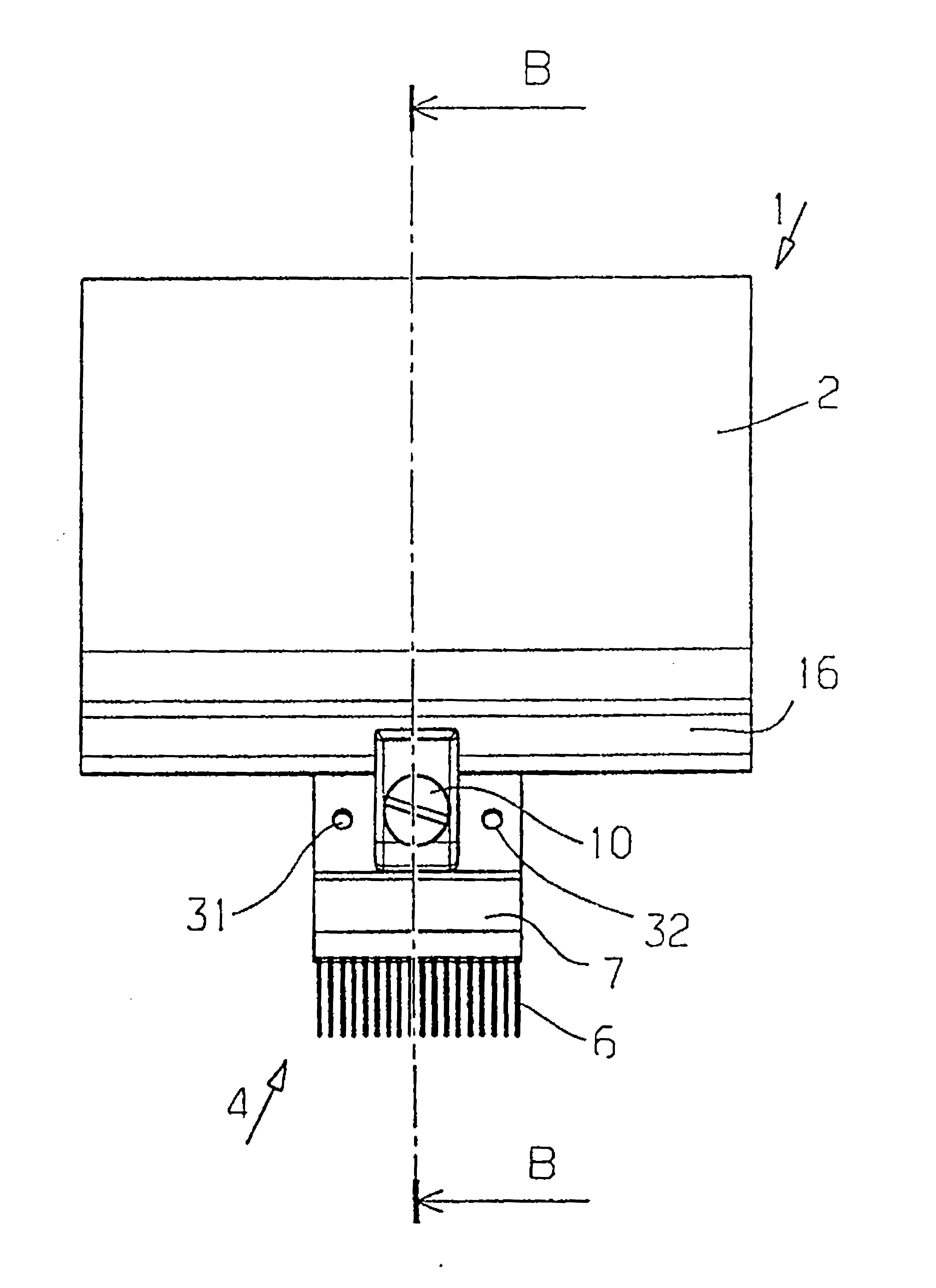
[0030] exist figure 1 The knitting tool bar 1 shown schematically in FIG. 1 is in the present case designed as a thread guide bar and has a main body 2 with an edge 3 . The braiding tool device 4 is fixed on the main body 2 . For this purpose, the main body 2 has a fastening area with an abutment surface 5, by figure 2 It can be seen that the braiding tool device 4 can be installed on the abutment surface.

[0031] The knitting tool device 4 has a plurality of knitting tools 6 , which in the present case are designed as eye needles and can thus be used as thread guide needles. The weaving tool 6 is collected in a weaving tool holder 7 . The braiding tool support 7 can generally also be referred to as a "base".

[0032] The braiding tool holder 7 has a through hole 8 into which an insert 9 is inserted from one side. A fastening screw 10 , which can also be referred to as a “fastener”, is guided through the insert 9 . The fastening bolt 10 is screwed into a clamping eleme...


PUM


Abstract

The tool bar has a knitting tool assembly (4) fixed to a fastening section (16) of a body (2). Edge of the body is adjacent to the knitting tool assembly to surround the fastening section in a clamping manner from outer side. The knitting tool assembly is engaged around the edge, and comprises a base or tool bar holder (7) and a clamping element, which is resiliently biased towards the base. The clamping element is actuated by a tightening device, and generates clamping force between the clamping element and the base, where clamping force is greater than spring bias.

Description

technical field [0001] The invention relates to a weaving tool bar with a main body and at least one weaving tool device fastened to a fastening region of the main body, wherein the main body has an edge adjacent to the weaving tool device. Background technique [0002] In order for knitting tools of the same type to move in the same way in a knitting machine, in particular a warp knitting machine, knitting tools of the same type are arranged on the knitting tool bar. Such bars extend across the working width of the weaving machine. The comb bars may therefore have a length of several meters at all. The working width and thus the bar length can now be 6 m. [0003] Such knitting tool bars must be accelerated and braked during each loop forming cycle. For this reason, it is striven to keep the mass of the knitting tool bar as small as possible. Instead of the early widespread use of light metals, such as magnesium or aluminum, in recent times mainly comb bars made of fibe...

Claims


Application Information

Patent Timeline
Patent Type & Authority Applications(China)
IPC IPC(8): D04B27/24
CPCD04B27/24
Inventor K.米斯塔
Owner KARL MAYER TEXTILMASCHFAB GMBH
Learn More