
Oil fume exhaust device for kitchen

A technology for exhausting oil fume and kitchen, which is applied in the field of kitchen oil fume exhaust devices, which can solve the problems that oil fume easily diffuses into the kitchen space, affects human health, pollutes the environment, etc., and achieves the effects of being beneficial to human health, easy to clean, and good effect

Inactive Publication Date: 2010-11-10
李其金
View PDF6 Cites 2 Cited by
  • Summary
  • Abstract
  • Description
  • Claims
  • Application Information

AI Technical Summary

Problems solved by technology

[0002]The effect of the fume exhaust device is related to the distance from the suction port to the source of the fume. At present, most of the fume exhaust devices commonly used in kitchens are upward exhaust structures. The range hood is installed above the cooker. Due to the large distance between the oil fume suction and exhaust port and the oil fume diffusion surface of the cooker, the oil fume is difficult to be completely gathered and sucked out, and it is easy to diffuse into the kitchen space, polluting the environment and affecting human health.

Method used


Image

  • Oil fume exhaust device for kitchen
  • Oil fume exhaust device for kitchen
  • Oil fume exhaust device for kitchen

Examples


Embodiment Construction

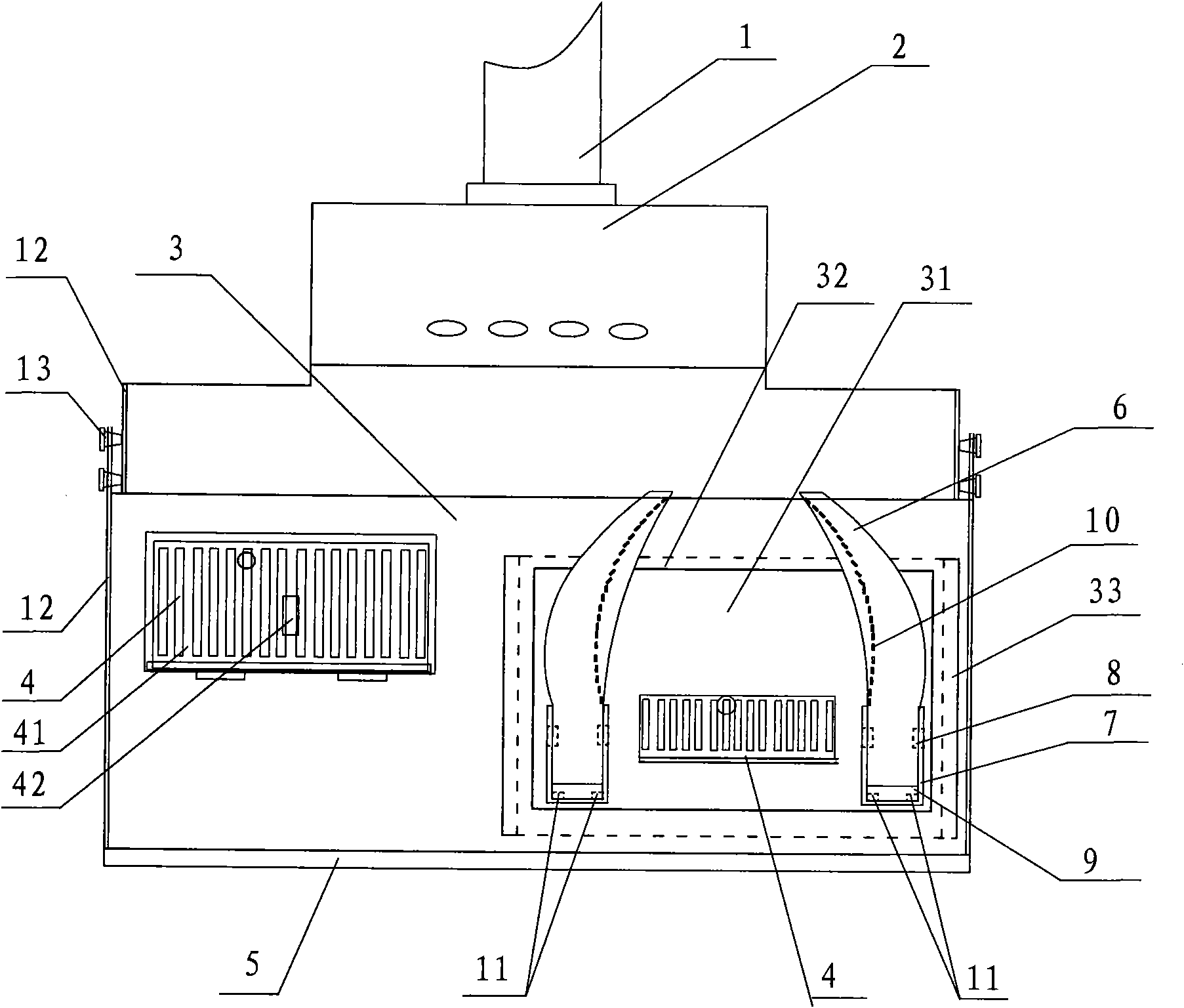
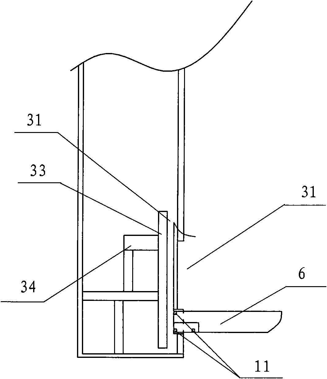
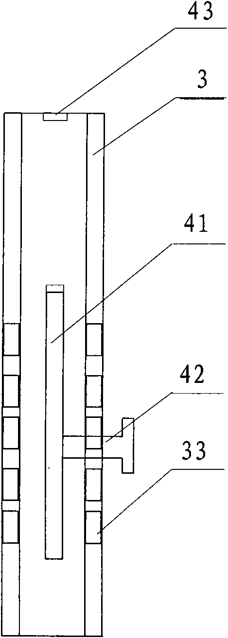
[0011] Now, the present invention will be described in detail in conjunction with the embodiments shown in the accompanying drawings.

[0012] like Figure 1-Figure 3 As shown, the kitchen oil fume exhaust device includes an oil fume exhaust outlet 1, an exhaust motor 2, and a collection flue. A smoke inlet hole 30 is installed on the collection flue panel 3 and a detachable smoke inlet hole plate 4 is movably connected by a rotating card. A movable smoke baffle 41 is installed on the smoke inlet plate 4, a movable handle 42 is installed on the movable smoke baffle 41, and a suction block 43 is installed at one end of the smoke inlet 41, and the movable handle of the movable smoke baffle 41 When 42 moves upwards, the movable smoke baffle 41 is sucked by the suction block 43, and the smoke inlet 30 is opened. When the moving handle 42 of the movable smoke baffle 41 moves downward, the smoke inlet 30 is closed, and the flue gas is collected. The bottom end is equipped with a de...


PUM


Abstract

The invention relates to an oil fume exhaust device for a kitchen, which is characterized by also comprising a combined flue plate. The lower end of a collecting flue panel is provided with a through hole; the combined flue plate is arranged in the through hole of the collecting flue panel; both sides of the combined flue plate are provided with guide tracks capable of moving up and down; the combined flue plate is arranged in the collecting flue panel through a guide track bracket; a rotating flue is arranged on the combined flue plate and comprises a rotating fume tube, a U-shaped fixed fume slot, a rotating shaft and an oil baffle plate; the lower end surface of the rotating fume tube is provided with an absorbable substance, and the absorbable substance is absorbed on the U-shaped fixed fume slot when the rotating fume tube is positioned on a vertical position; and in addition, a collecting flue can be horizontally divided into an upper collecting flue and a lower collecting flue, both sides of the upper collecting flue and the lower collecting flue are respectively connected with slide tracks, the slide tracks are mutually connected and positioned through retaining screws, and the upper collecting flue is sleeved into the lower collecting flue. When in use, the height of the rotating fume tube can be regulated freely as required and the invention has the advantages of cleaner oil fume exhaust, kitchen environment pollution prevention, human health favorableness, convenient use and easy cleaning.

Description

technical field [0001] The invention relates to an oil fume exhaust device, in particular to a kitchen oil fume exhaust device Background technique [0002] The use effect of the oil fume exhaust device is related to the distance from the suction port to the source of the oil fume. At present, most of the oil fume exhaust devices commonly used in the kitchen are of the upper exhaust structure. The range hood is installed above the cooker. The distance between the fume diffusion surfaces is relatively large, and it is difficult for the fume to be completely gathered and sucked out, and it is easy to diffuse into the kitchen space, pollute the environment, and affect human health. Contents of the invention [0003] The object of the present invention is to provide an easy-to-use kitchen fume exhaust device with good effect in order to overcome the above-mentioned disadvantages of the prior art. [0004] The technical solution of the present invention is: the kitchen oil fum...

Claims


Application Information

Patent Timeline
Patent Type & Authority Applications(China)
IPC IPC(8): F24C15/20
Inventor 李其金
Owner 李其金
Learn More