
A method for interference rejection

A pole, weighted technique applied to electrical components, antennas, etc.

Inactive Publication Date: 2010-11-10
TELEFON AB LM ERICSSON (PUBL)
View PDF3 Cites 1 Cited by
  • Summary
  • Abstract
  • Description
  • Claims
  • Application Information

AI Technical Summary

Problems solved by technology

The interfering signal may be in close proximity (in azimuth) to the desired signal, causing problems

Method used


Image

  • A method for interference rejection
  • A method for interference rejection
  • A method for interference rejection

Examples


Embodiment Construction

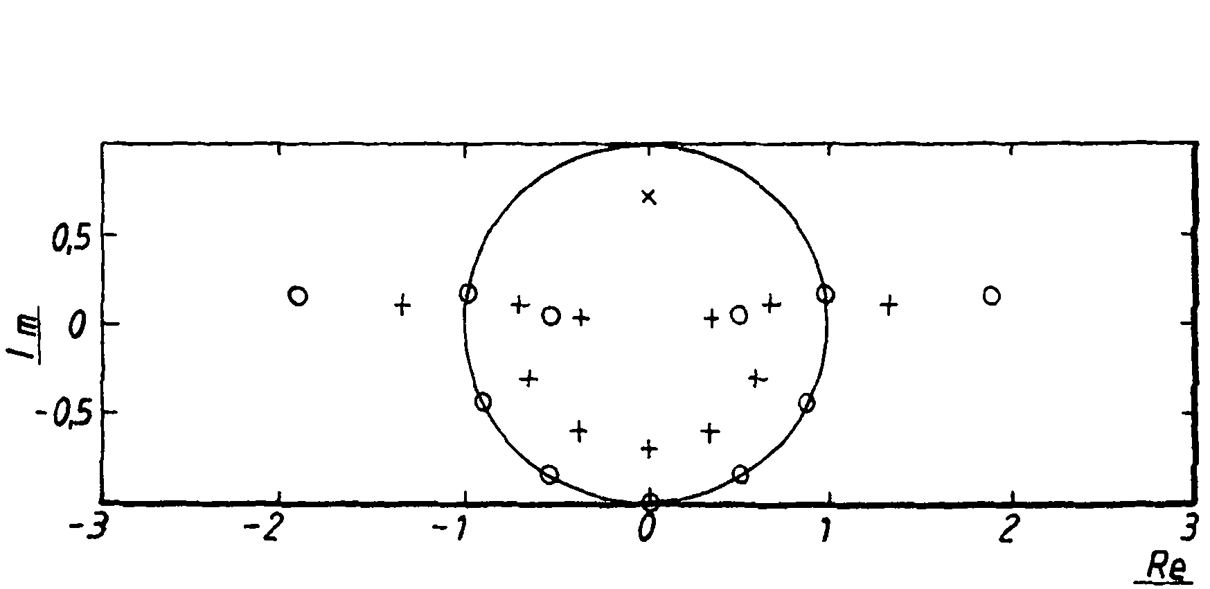
[0019] In general, an alternative model for interfering signals from scatterers is the source of power in the angular spectrum. The source can be modeled by introducing a pole model in the angular domain. From a system function point of view, the antenna array can be represented by zeros in the complex plane. Likewise, poles can be inserted into this plane. This means that, for a single pole, the angle with respect to the real axis defines the direction, and the distance from the origin defines the extension. The essence in the pole model lies in the fact that it represents a cluster with infinitely many scatterers, yet is still modeled by one parameter.

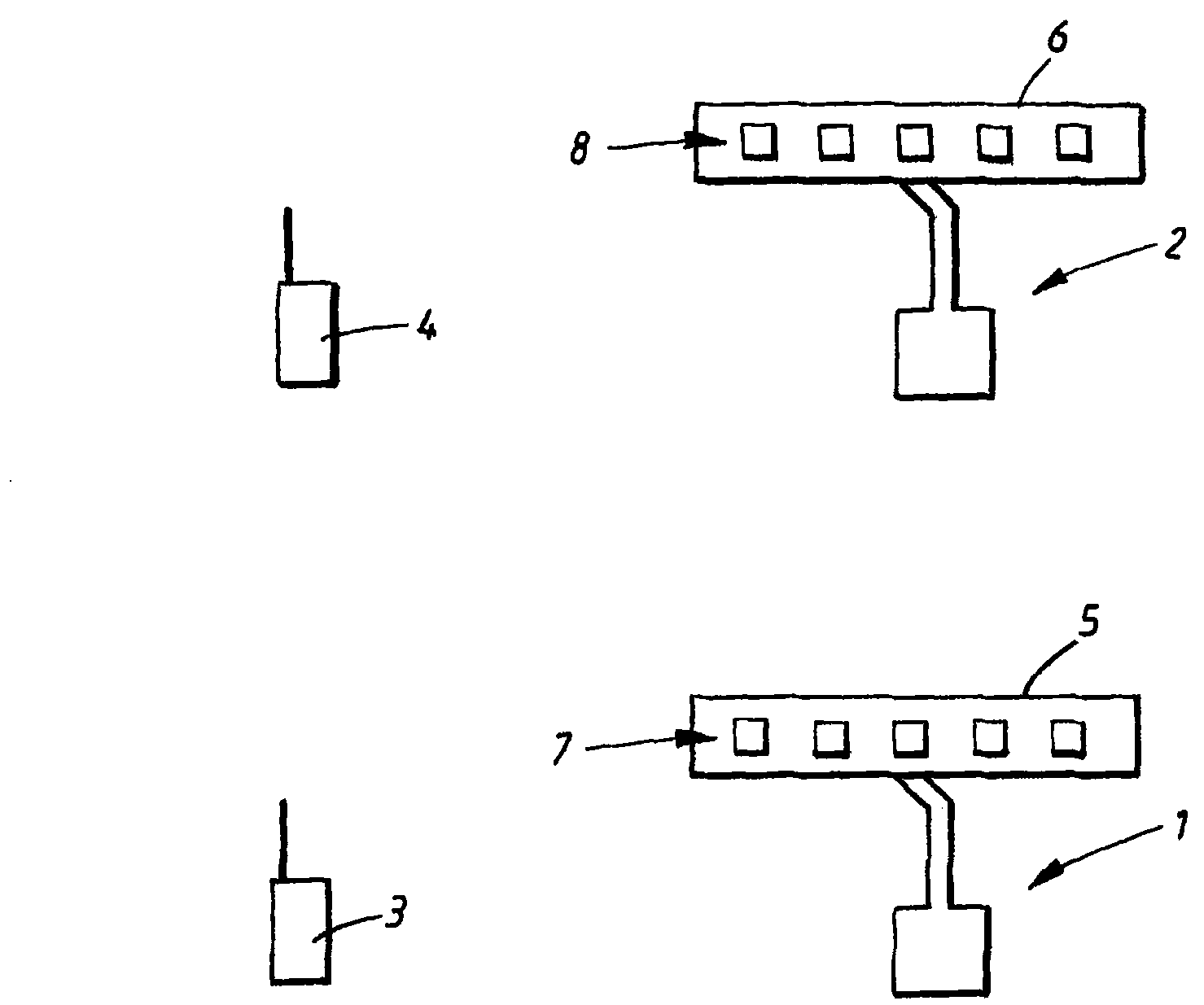
[0020] will now refer to figure 1 , giving a more detailed description of an embodiment of the present invention.

[0021] In a certain area, a first base station 1 and a second base station 2 exist. The base stations 1,2 are arranged to communicate with mobile stations 3,4. The first base station 1 and the second base...


PUM


Abstract

The present invention relates to a method for identifying components in a telecommunication system, which method comprises the steps representing a uniform linear array, ULA, antenna (5), having at least two antenna elements, by an array factor polynomial comprising at least two terms, each term having a certain weight (wK); setting said weights (wK) to desired values such that a desired antenna radiation pattern is acquired. Furthermore, the method comprises the steps: changing the desired weights such that a number of sets of desired weights (wK) is acquired, such that the ULA antenna (5) scans a spatial portion, a certain scan corresponding to a certain set of desired weights, analyzing a received signal (h0) being represented by a received array factor polynomial having terms with certain received weights, which is parameterized by at least one pole; and using each corresponding set of desired weights (wK) and received weights to determine the pole parameterization.

Description

technical field [0001] The invention relates to a method for identifying components in a telecommunication system, the method comprising the steps of representing a uniform linear array ULA antenna with at least two antenna elements by an array factor polynomial comprising at least two terms, each with some weight, and the weights are set to desired values ​​to obtain the desired antenna radiation pattern for the ULA antenna corresponding to the desired array factor polynomial. Background technique [0002] In telecommunications, one or more base stations communicate with mobile stations such as mobile phones and laptop computers. Typically, mobile stations are modeled by clusters of so-called local scatterers. This cluster is the collection of scatterers close to the transmitting mobile, where the term "close" should be interpreted as a distance corresponding to a time much smaller than the symbol time. The scatterers that make up the cluster will create a signal distribu...

Claims


Application Information

Patent Timeline
Patent Type & Authority Applications(China)
IPC IPC(8): H01Q3/26
CPCH01Q3/2605H01Q3/26
Inventor U·林德格伦
Owner TELEFON AB LM ERICSSON (PUBL)
Learn More