Acoustic transducer

A technology of acoustic transducers and drivers, applied in the direction of transducer circuits, transducers applying multiple principles, sensors, etc., can solve problems such as expensive, dependent, and bulky

Active Publication Date: 2010-11-10
HARMAN BECKER GEPKOCSIRENDSZER GYARTO KORLATOLT FELELOSSEGU TARSASAG
View PDF4 Cites 18 Cited by
  • Summary
  • Abstract
  • Description
  • Claims
  • Application Information

AI Technical Summary

Problems solved by technology

Although permanent magnets consume no energy, they have a limited energy product (B

Method used


Image

  • Acoustic transducer
  • Acoustic transducer
  • Acoustic transducer

Examples


Embodiment Construction

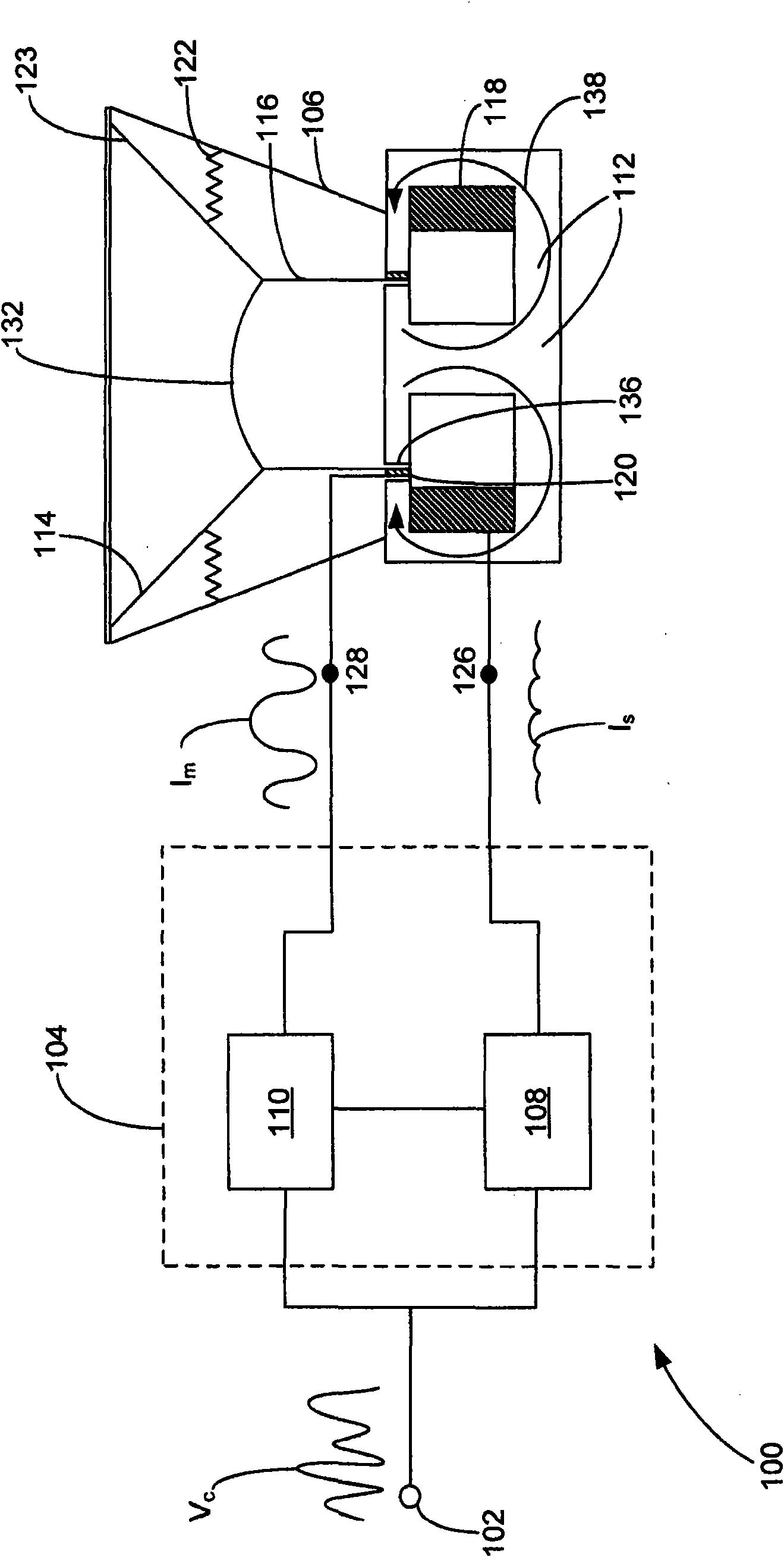
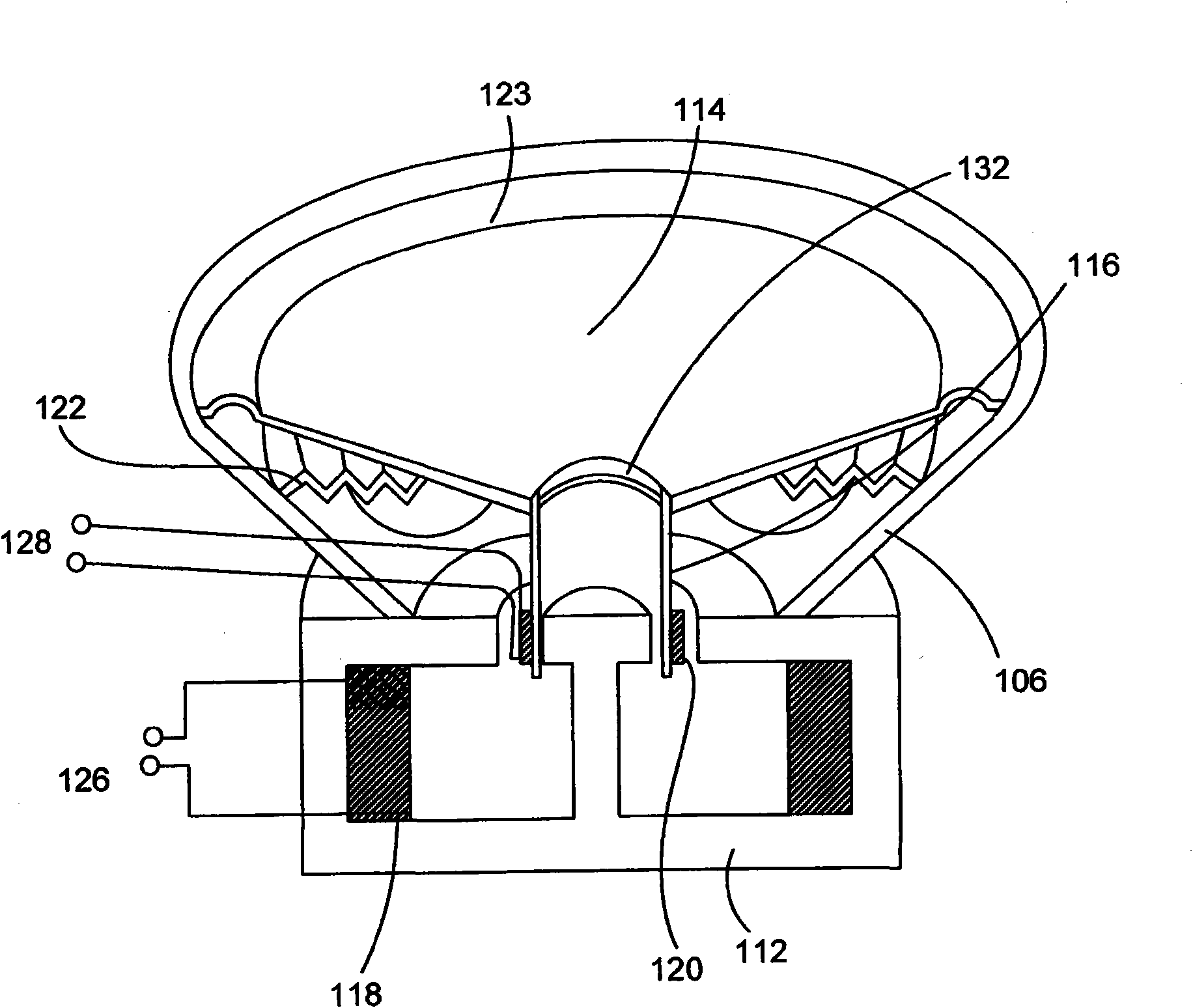
[0027] first reference figure 1 , which shows an acoustic transducer 100 according to some embodiments of the invention. The transducer 100 has an input terminal 102 , a control block 104 and a driver 106 . figure 1 Driver 106 is shown in cross-section and the remainder of transducer 100 is shown in block diagram.

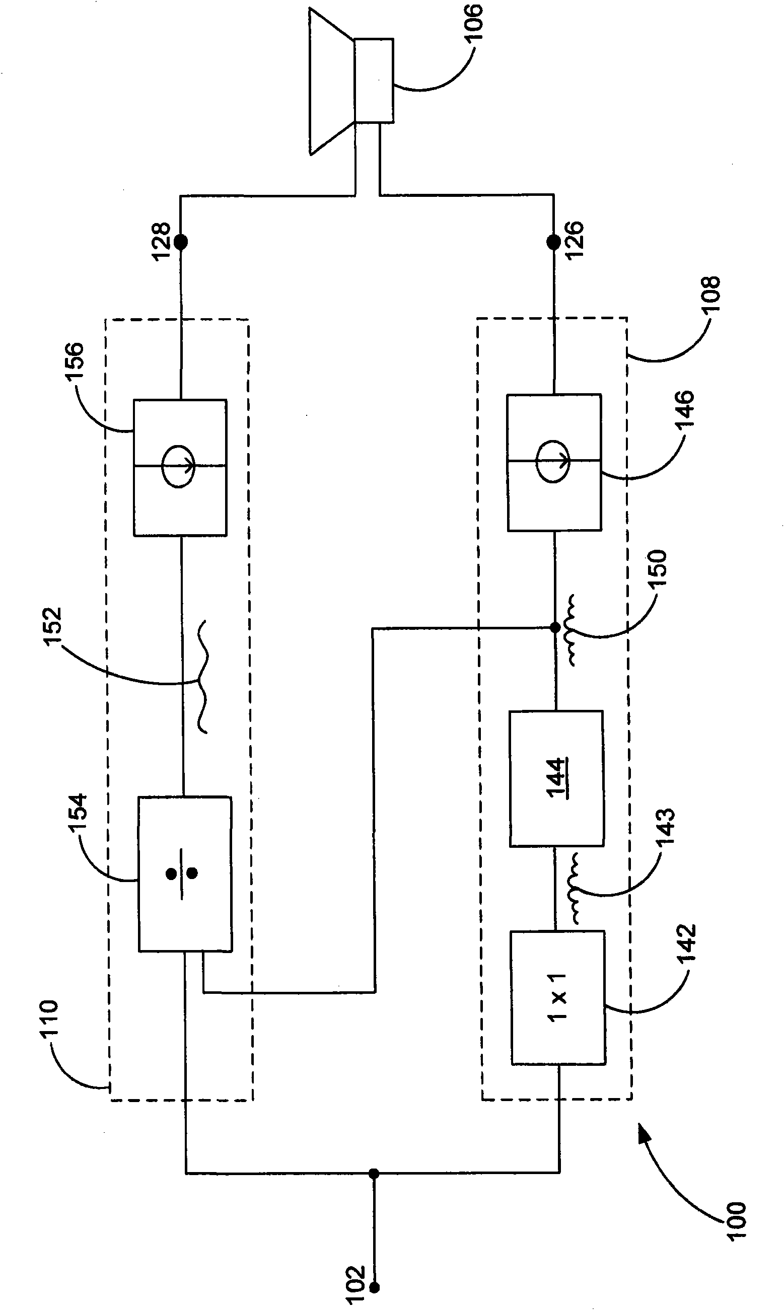
[0028] The control block 104 includes a stationary coil signal generation block 108 and a moving coil signal generation block 110 . Each of the stationary coil signal generating block and the moving coil signal generating block is coupled to an input terminal 102 . In operation, the input audio signal V i Received at input terminal 102 and transmitted to stationary coil signal generation block 108 and moving coil signal generation block 110 . Stationary coil signal generation block 108 responds to the input signal V i while at node 126 generates a fixed coil signal I s . Similarly, the moving coil signal generation block 110 responds to the input signal V ...


PUM


Abstract

This invention relates to acoustic drivers with stationary and moving coils. Time varying signals are applied to the moving and stationary coils to control the movement of a diaphragm, which produces audible sound. The time varying signals correspond to an input audio signal such that the sound corresponds to the input audio signal. Some of the described embodiments include multiple moving coils, multiple stationary coils or both. Some embodiments include feedback for adjusting one or more of the signals based on a characteristic of the acoustic driver. Various compensation and other features of the invention are also described in relation to various embodiments.

Description

[0001] Cross References to Prior Applications [0002] This application claims the benefit of US Provisional Patent Application No. 60 / 975,339, which is incorporated herein by reference. technical field [0003] Embodiments described herein relate to acoustic transducers. Background technique [0004] Many acoustic transducers or drivers use moving coil dynamic drivers to generate sound waves. In most transducer designs, the magnets provide the flux path with an air gap. The moving coil interacts with the magnetic flux in the air gap to move the actuator. Initially, electromagnets were used to create fixed magnetic flux paths. These electromagnet-based drives suffer from high energy consumption and losses. More recently, acoustic drivers have been made from permanent magnets. Although permanent magnets consume no energy, they have a limited energy product (BH product), can be bulky, and rely on magnetic materials, they can also be expensive. In contrast, electromagnet-...

Claims


Application Information

Patent Timeline
IPC IPC(8): H04R3/00H04R9/06
CPCH04R3/00H04R9/06H04R9/025H04R9/04H04R2209/024H04R9/027H04R13/00H04R23/02
Inventor J·B·弗伦奇A·J·梅森
Owner HARMAN BECKER GEPKOCSIRENDSZER GYARTO KORLATOLT FELELOSSEGU TARSASAG
Why Eureka
Try Eureka