Mobile lighting mechanism

A mobile, contact mechanism technology, used in instruments, nonlinear optics, optics, etc., can solve problems such as time consumption

Inactive Publication Date: 2010-11-17
CONTREL TECH CO LTD
View PDF0 Cites 23 Cited by
  • Summary
  • Abstract
  • Description
  • Claims
  • Application Information

AI Technical Summary

Problems solved by technology

[0004] However, the above-mentioned method is carried out separately on two machines, and the LCD panel must be moved from the scanner to the laser repairing machine after scanning, and then the repaired LCD panel is moved to the storage place. The process

Method used


Image

  • Mobile lighting mechanism
  • Mobile lighting mechanism
  • Mobile lighting mechanism

Examples


Embodiment Construction

[0011] In order to describe in detail the structure and features of the present invention, the following is a preferred embodiment and is illustrated in conjunction with the drawings, in which:

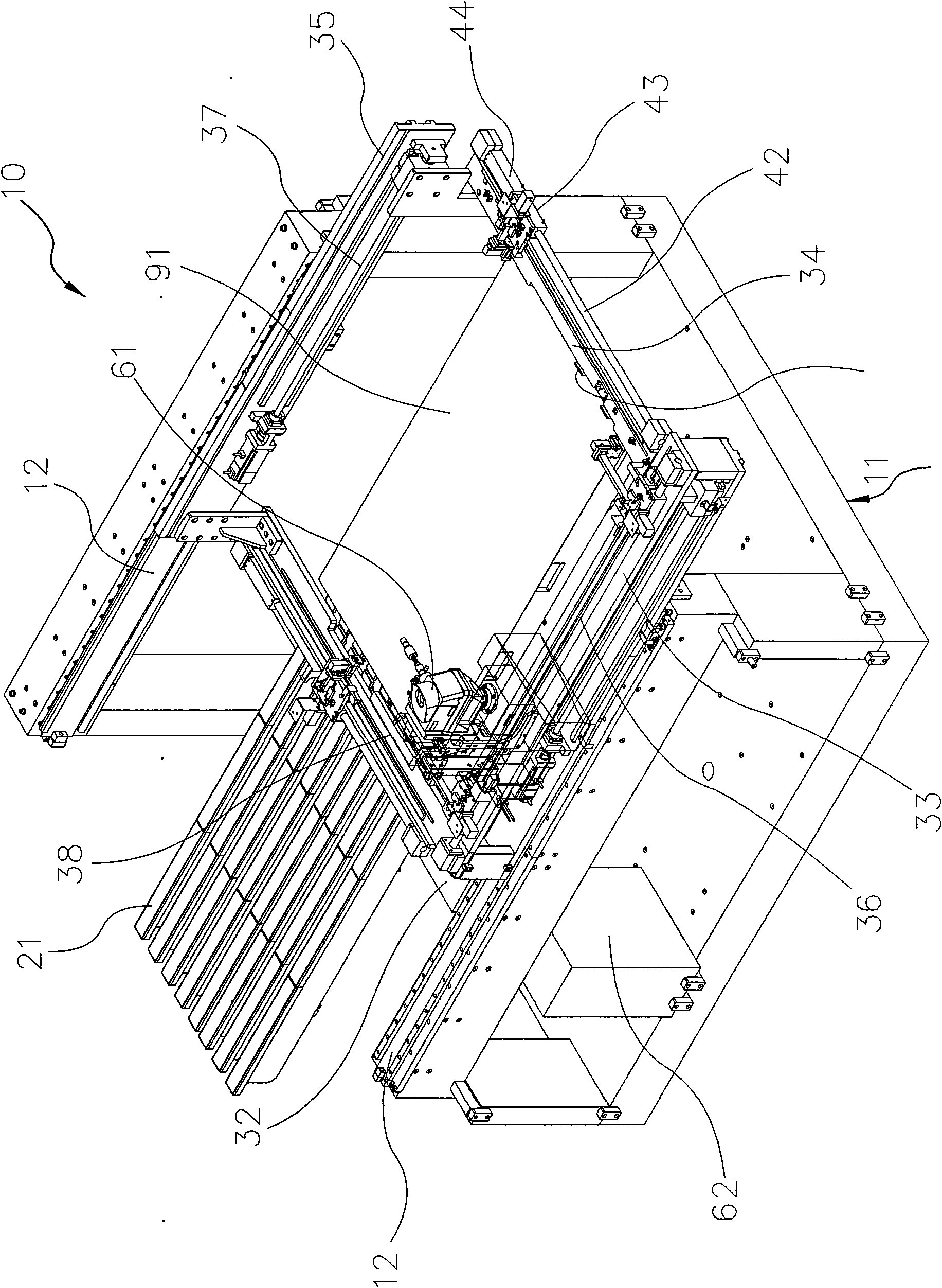
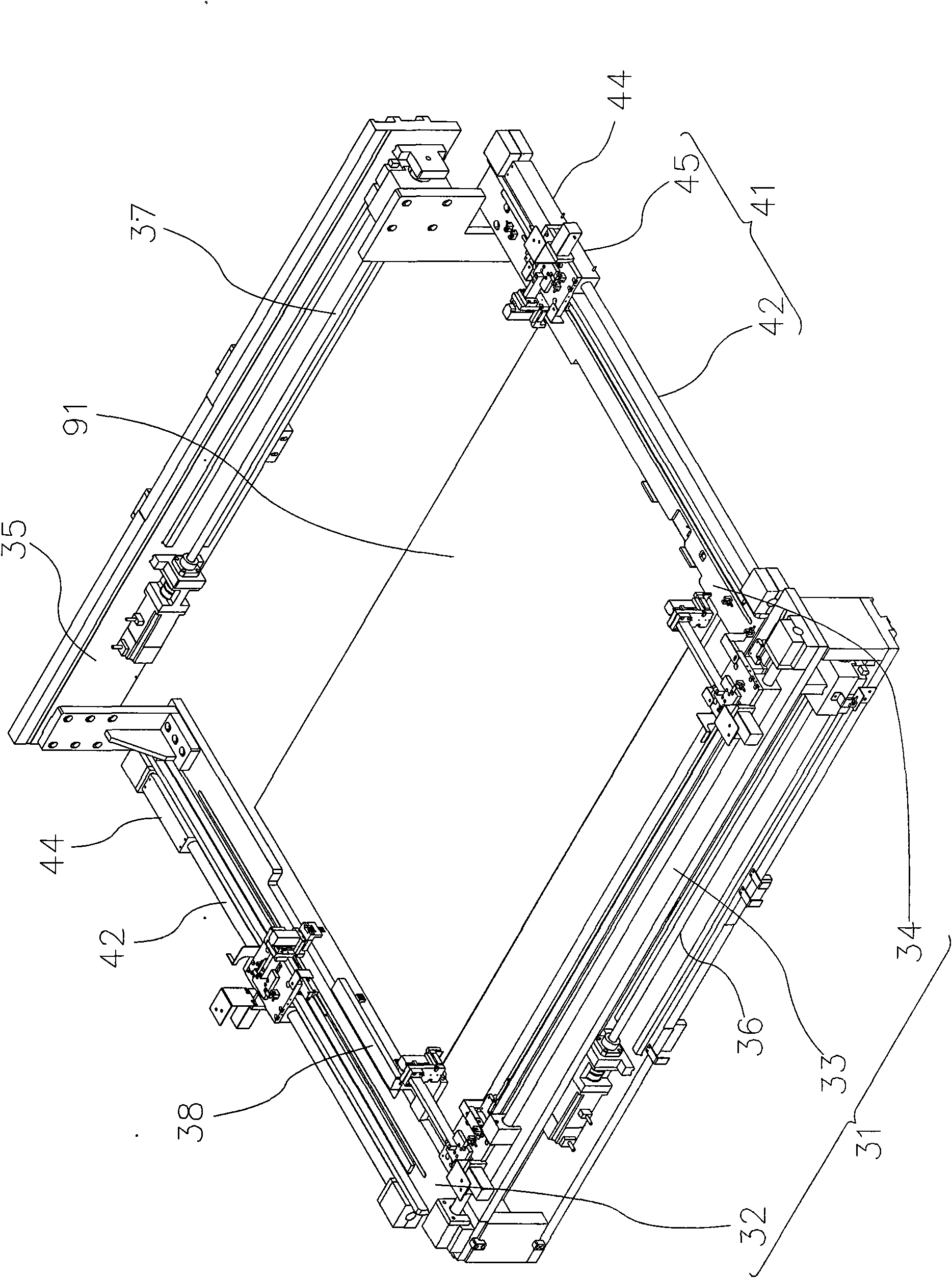
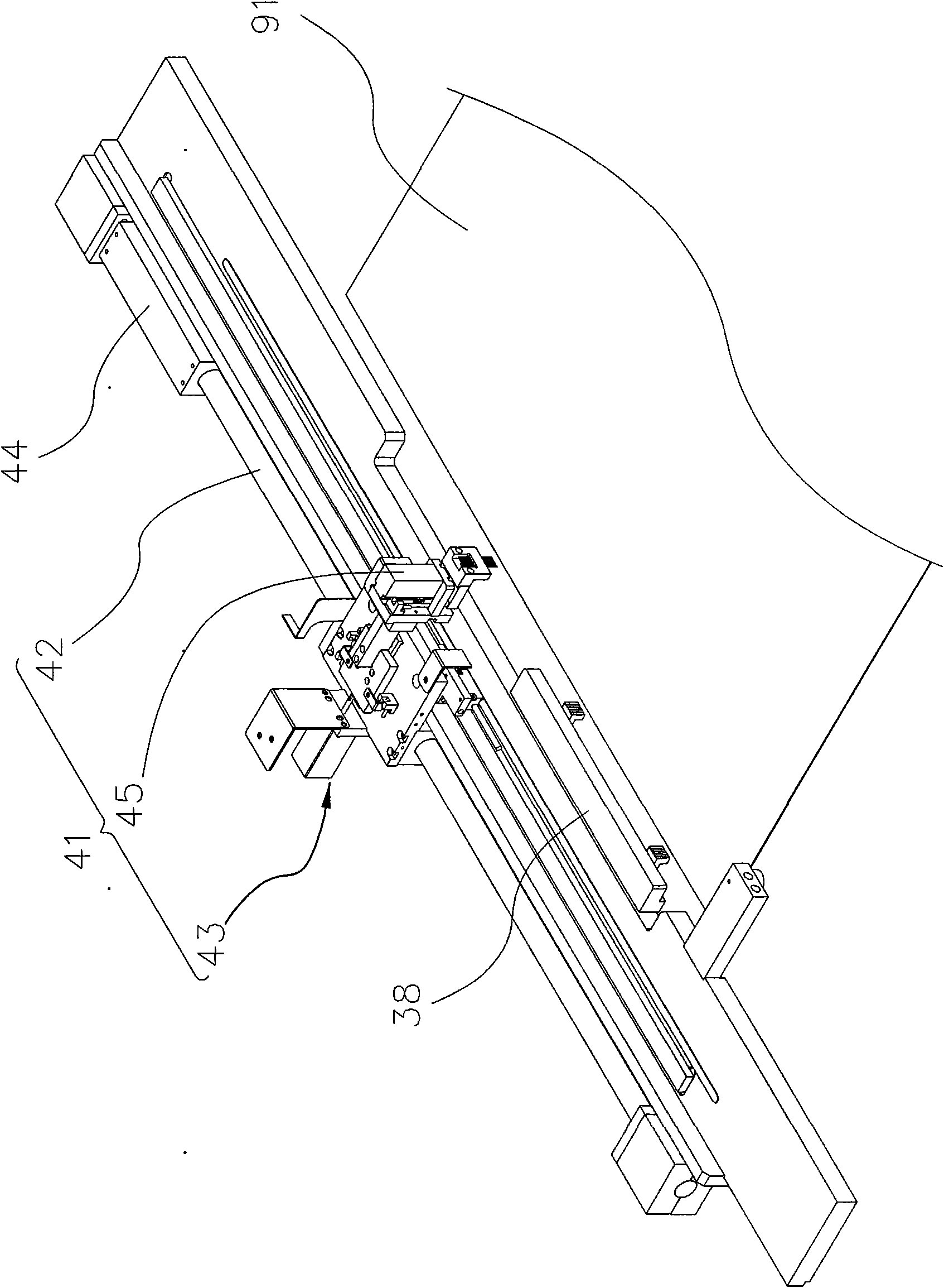
[0012] Such as Figure 1 to Figure 4 As shown, a mobile lighting mechanism 10 provided by the first preferred embodiment of the present invention includes: a machine table 11, a bearing table 21, a U-shaped frame 31, and a light test mechanism 41; The platform 11 is provided with a linear slide rail 12 along the X axis; the bearing platform 21 is arranged on the machine platform 11 for receiving a liquid crystal panel 91, the bearing platform 21 is an air floating platform, which sprays gas upward to The liquid crystal panel 91 is in an air-floating state; the U-shaped frame 31 is erected on the linear slide rail 12, and can be moved along the X axis on the machine table 11 by a driving device. The U-shaped frame 31 has an edge Y A first frame 32 arranged along the X axis, a second fram...


PUM


Abstract

The invention discloses a mobile lighting mechanism, which comprises a machine station, a bearing table, a U-shaped framework and a lighting test mechanism, wherein the bearing table is arranged on the machine station and used for bearing a liquid crystal panel; the U-shaped framework is erected on the machine station and moves on the machine station along the X axis by means of a driving device; and the lighting test mechanism is provided with a quick contact mechanism, and the quick contact mechanism is arranged on the U-shaped framework, provided with a lifting head and used for performing lighting test on the liquid crystal panel on the bearing table. By utilizing the mechanism, the panel can perform repair and conveying operation at the same time so as to achieve the effects of promoting the efficiency of the repair operation and reducing the repair cost.

Description

Technical field [0001] The present invention relates to a repairing device for liquid crystal panels, in particular to a movable lighting mechanism. Background technique [0002] It is currently known that during the manufacturing process of liquid crystal panels, it must be illuminated to scan for flaws. If the flaws are scanned, they are then repaired through a laser repair procedure. [0003] In the traditional way, the scanning and laser light repair procedures for the defects on the LCD panel are carried out separately on two machines (scanner and laser repair machine), and the operator first uses the scanner to check one The LCD panel is lit and scanned to obtain the coordinates of the defect; after that, the defect coordinates of the LCD panel are input to the laser repair machine, and the LCD panel is transported to the laser repair machine, and then After the position is calibrated, the defect can be laser repaired according to the coordinate after the position is accurat...

Claims


Application Information

Patent Timeline
IPC IPC(8): G02F1/13
Inventor 叶公旭张志逢苏纪豪陈建宏
Owner CONTREL TECH CO LTD
Why Eureka
Try Eureka