Device for displaying running state of equipment

A technology for operating status and displaying equipment, applied in the direction of identification devices, instruments, computer control, etc., can solve the problems that it is difficult to achieve different states of equipment, and can not do remote workshop-level global status monitoring, so as to reduce equipment downtime losses and improve Production efficiency, the effect of improving service efficiency

Inactive Publication Date: 2010-11-17
HANGZHOU C&U CONTROL SYST
View PDF3 Cites 5 Cited by
  • Summary
  • Abstract
  • Description
  • Claims
  • Application Information

AI Technical Summary

Problems solved by technology

[0002] In modern industrial production, the following two methods are mainly used for real-time monitoring of the operation status of all equipment in the workshop: the first method is to connect multi-color display lights to the equipment, and transmit the relevant signals of the equipment to the multi-color display lights through cable connections. Directly display the running status of the equipment. The disadvantage of this method is that it can only indicate the status of the current equipment near the physical location of the equipment, and cannot do remote workshop-level global status monitoring: the second method uses remote software indication way, including at least on-site data acquisition hardware system, microprocessor and LED display, connected to the microprocessor through electrical signals, and equipment simulation diagrams or multiple color block indicators on the microprocessor or network display device To indicate the status of the equipment, it can realize the remote whole workshop level global status monitoring, but because of the limitations of the display method, the number of displayed equipment is limited, and the number of more than a few or dozens of equipment must be realized through screen switching. It is difficult to display the different states of all the equipment in the workshop on one display interface

Method used


Image

  • Device for displaying running state of equipment
  • Device for displaying running state of equipment
  • Device for displaying running state of equipment

Examples


Embodiment Construction

[0016] The present invention will be described in detail below in conjunction with the accompanying drawings: a device for displaying the operating state of the equipment, including a field data acquisition hardware system, a microprocessor and an LED display screen, and the described field data acquisition hardware system transmits data to the LED through the microprocessor. The display screen sends the status information of the device, and the LED display screen is arranged with square LED plane combined color block lights in a matrix.

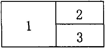
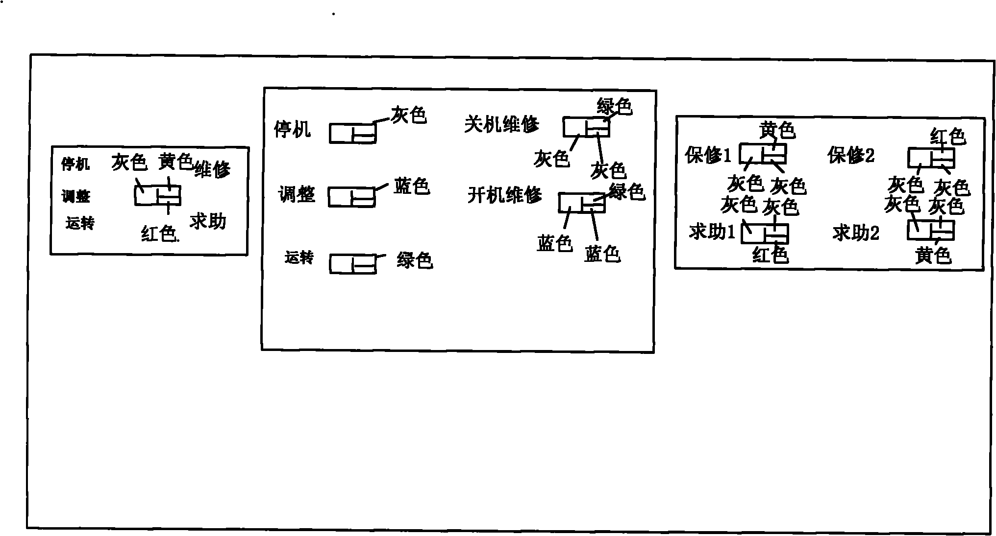
[0017] Such as Figures 1 to 3 As shown, a single LED plane combination color block light is divided into three color block areas, different color block areas display different colors, and the three color block areas can flash at different frequencies. The overall combination of color blocks is defined as area 1, The upper right corner of the color block is defined as area 2, the lower right corner of the color block is defined as area 3, an...


PUM


Abstract

The invention relates to a device for displaying the running state of equipment. The device comprises a field data acquisition hardware system, a microprocessor and an LED display screen, wherein the field data acquisition hardware system sends state information of the equipment to the LED display screen through the microprocessor; square LED plane combined color lump lamps are distributed on the LED display screen in a matrix form; the single LED plane combined color lump lamp is divided into three color lump areas, each color lump area can display different colors, and the three color lump areas can sparkle with different frequencies; and the combined color lump lamps can perform dynamic variation according to the state of the equipment, so that one display device can display multiple kinds of state information of multiple equipment, the information transfer efficiency is improved, and remote and all workshop-level overall state monitoring is realized.

Description

technical field [0001] The invention relates to a device for displaying the running state of equipment, in particular to a device for displaying the running state of the equipment by using combined color blocks. Background technique [0002] In modern industrial production, the following two methods are mainly used for real-time monitoring of the operation status of all equipment in the workshop: the first method is to connect multi-color display lights to the equipment, and transmit the relevant signals of the equipment to the multi-color display lights through cable connections. Directly display the running status of the equipment. The disadvantage of this method is that it can only indicate the status of the current equipment near the physical location of the equipment, and cannot do remote workshop-level global status monitoring: the second method uses remote software indication way, including at least on-site data acquisition hardware system, microprocessor and LED disp...

Claims


Application Information

Patent Timeline
Patent Type & Authority Applications(China)
IPC IPC(8): G05B19/048G09F9/33
Inventor 章近达鲍敏
Owner HANGZHOU C&U CONTROL SYST
Why Eureka
Try Eureka