
System and method for micro telecommunication computing architecture hot-plug control

A telecommunications computing and control system technology, applied in the field of communication, can solve the problems of increasing the difficulty and cost of backplane wiring

Inactive Publication Date: 2012-05-02
韩梁 +1
View PDF0 Cites 0 Cited by
  • Summary
  • Abstract
  • Description
  • Claims
  • Application Information

AI Technical Summary

Problems solved by technology

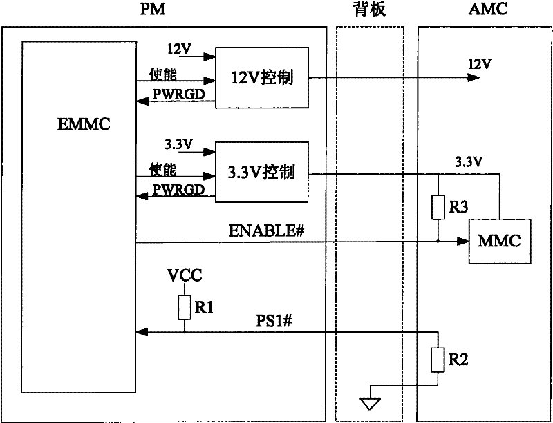
[0020] Since there is a pair of PS1# and ENABLE# signals between each PM and AMC, MCH, and CU, when there are multiple PMs connected to multiple AMCs, MCHs, and CUs, a large number of signal lines (such as 4 PMs and 2 When one MCH, two CUs and 12 AMCs are connected, (2+2+12)*2*4=128 signal lines are required; if the AMC is also expanded, that is, the number of AMCs is increased, more signal lines are required ), therefore, increasing the difficulty and cost of backplane wiring

Method used


Image

  • System and method for micro telecommunication computing architecture hot-plug control
  • System and method for micro telecommunication computing architecture hot-plug control
  • System and method for micro telecommunication computing architecture hot-plug control

Examples


Embodiment 1

[0045] see Figure 2A , Embodiment 1 of the system of the present invention provides a MicroTCA hot-swap control system, including:

[0046] The first veneer 21, the second veneer 22;

[0047] The in-position signal line (PS1#) of the first single board 21 is connected to the enable signal line (ENABLE#) of the first single board 21 and then connected to the control signal line of the second single board 22;

[0048] The control signal line adopts a bidirectional control method:

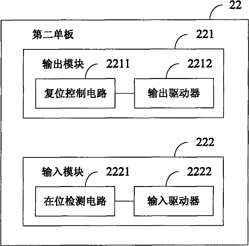
[0049] The second veneer 22 receives an in-position signal from the in-position signal line through the control signal line, for detecting whether the first veneer 21 is in position;

[0050] The second single board 22 sends a reset signal to the enable signal line through the control signal line for resetting the management controller of the first single board 21 .

[0051] Wherein, the first single board 21 is a micro-telecom computing architecture main control switching unit (MCH), or a cooling...

Embodiment 2

[0067] Embodiment 2 of the present invention provides a MicroTCA hot swap control system, the MicroTCA system includes a first board and a second board, wherein the first board can be AMC, MCH or CU; the second board can be PM. PS1# of the first board is connected to ENABLE# and then connected to the control signal line of the second board. Since the control signal line corresponds to the control signal transmitted thereon, in the following, no strict distinction is made between the control signal line and the control signal.

[0068] The MicroTCA in this embodiment of the present invention may further include a backplane. PS1# and ENABLE# of the first single board may be connected to the control signal of the second single board on the backplane after being connected to the backplane. The PS1# and ENABLE# of the first board can also be connected on the first board first, and then the connected signal line is connected with the control signal line of the second board on the b...


PUM


Abstract

The embodiment of the invention discloses a system and a method for micro telecommunication computing architecture hot-plug control. The system comprises a first single board and a second single board; an in-place signal wire and an enabling signal wire of the first single board are connected and then connected with a control signal wire of the second single board; and the control signal wire adopts a bidirectional control mode, namely the second single board receives an in-place signal of the in-place signal wire through the control signal wire to detect whether the first single board is in place, and the second single board sends a reset signal to the enabling signal wire through the control signal wire to reset a management controller of the first single board. The in-place signal wireand the enabling signal wire of the first single board are connected and then connected with the control signal wire of the second single board, thereby simplifying system wiring and reducing the development cost.

Description

technical field [0001] The invention relates to the field of communication technology, in particular to a micro-telecom computing architecture hot-swap control system and method. Background technique [0002] With the rapid development of communication services and the continuous improvement of network bandwidth, operators have put forward higher requirements for the performance, openness, reliability, manageability and scalability of hardware platforms; at the same time, in order to adapt to small and medium capacity, low Cost, relatively low availability of telecommunications and enterprise applications, PICMG (PCI Industrial Computers Manufacturers Group, PCI Industrial Computer Manufacturers Association) organization borrowed some design concepts from ATCA (Advanced Telecommunications Computing Architecture, Advanced Telecommunications Computing Architecture) to AMC (Advanced Based on the Mezzanine Card (advanced mezzanine card) plug-in card, a new type of small-sized ha...

Claims


Application Information

Patent Timeline
Patent Type & Authority Patents(China)
IPC IPC(8): G06F13/40
Inventor 李延松
Owner 韩梁
Learn More