Hydraulic upsetter

A kind of upsetting machine and hydraulic technology, applied in the field of hydraulic upsetting machine, to achieve the effect of fast action speed, large upsetting force and wide application

Active Publication Date: 2010-11-24
葫芦岛龙源采油配套设备有限公司
View PDF7 Cites 10 Cited by
  • Summary
  • Abstract
  • Description
  • Claims
  • Application Information

AI Technical Summary

Problems solved by technology

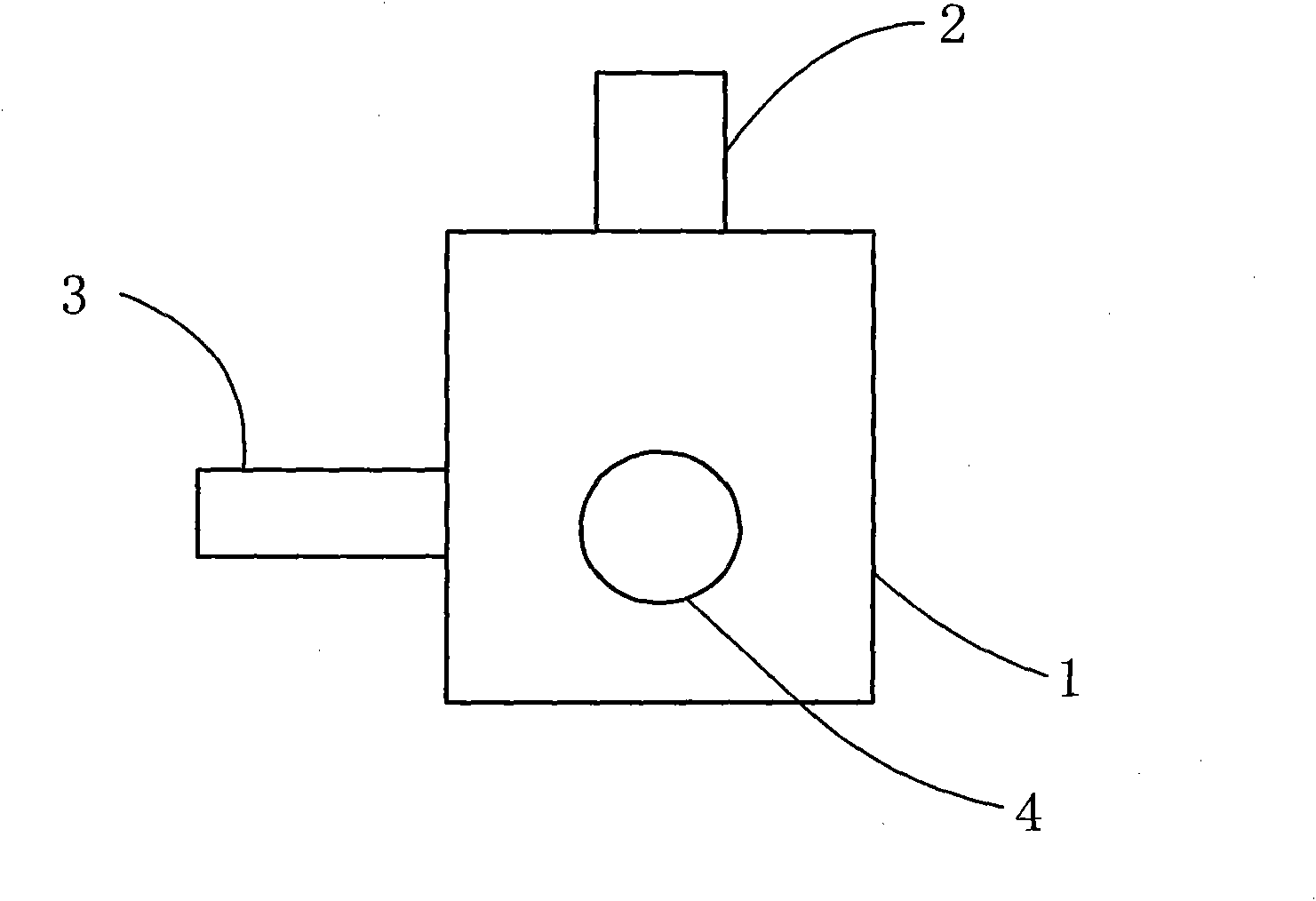
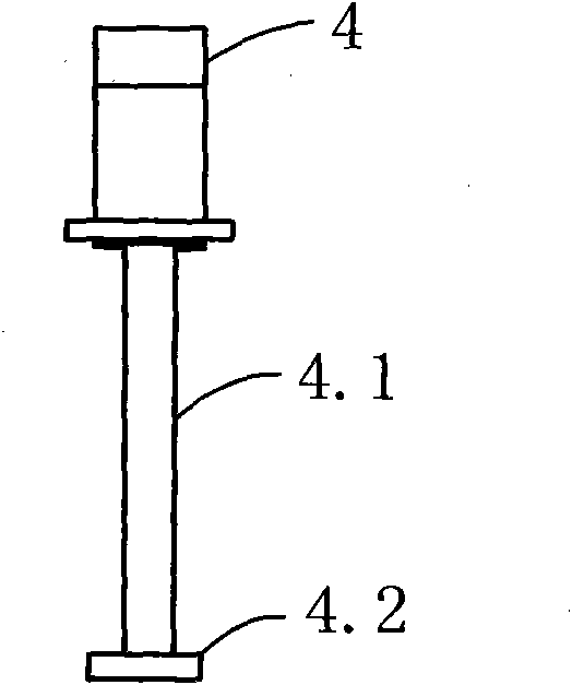
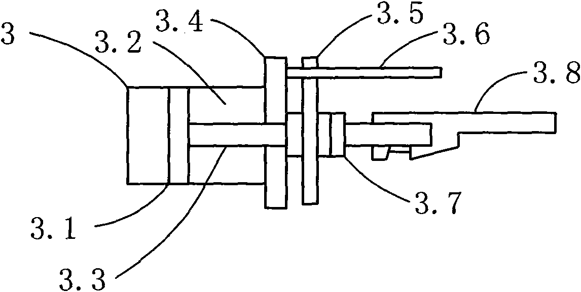
The device fixes the upsetting mold in different directions and applies pressure to the workpiece. The working oil cylinder is controlled and operated through the controller to solve the technical problems of rapid upsetting and extrusion of the workpiece and the operation and control of the connecting cable.

Method used


Image

  • Hydraulic upsetter
  • Hydraulic upsetter
  • Hydraulic upsetter

Examples


Embodiment

[0080] Taking the rod-shaped workpiece as an example, firstly, put the clamping cylinder plunger at the rear starting point, the upsetting cylinder plunger at the rear starting point, and the lifting cylinder plunger at the upper starting point, heat the rod head to 1100°C and put it into the tire cavity, lift The cylinder plunger moves downward to close the mold, the clamping cylinder plunger moves forward to tighten the upper and lower tire molds through the wedge, the lifting cylinder plunger returns to the upper starting point to open the mold, the clamping cylinder plunger returns to the rear starting point, and the extrusion cylinder The plunger returns to the back starting point, the plunger of the upsetting extrusion cylinder moves forward, the punch rod enters the tire mold, the rod head is upset and extruded, and the workpiece is taken out.

[0081] The above actions are automatically completed by interlocking, and the whole process of upsetting and extrusion takes 8-...


PUM


Abstract

The invention provides a hydraulic upsetter, wherein a die oil cylinder is arranged above a rack, an upset-extruding oil cylinder is installed at one side of the rack, and a push-wedge oil cylinder is installed at a position 90-degree adjacent to the rack; and the oil cylinders respectively and jointly locate, lock and extrude a workpiece in an upset-extruding mould to realize upset-extrusion processing on the workpiece. The hydraulic upsetter of the invention compresses the mould through the die oil cylinder, fixes the mould through the push-wedge oil cylinder and carries out upsetting process on the workpiece through the upset-extruding oil cylinder, and realizes coordinated control and operation through an electromagnetic controller. The hydraulic upsetter has the advantages of large upsetting extrusion force, quick movement speed, good processing quality, energy conservation and wide application range, and is suitable for being applied in upsetting extrusion process on workpieces in the filed of machining.

Description

technical field [0001] The present invention proposes a processing machine in the mechanical field, specifically a hydraulic upsetting machine. Background technique [0002] At present, the forming forging equipment produced in our country, such as flat forging machine, can only forge solid sucker rods of Φ19-Φ25, but cannot forge hollow sucker rods and oil pipes. Other vertical hydraulic presses can only die forge various shorter parts. [0003] At present, the machines used for thickening or shrinking and reaming the ends of metal pipes and rods are mainly forging presses or molding presses, which can only apply pressure from one end to make the processed materials form a certain structural shape. Some of the pressure is realized by pressing the stamping rod that slides up and down through the rotation of the cam to press on the workpiece. In addition, the workpiece is pressed by the push of the screw, so as to realize the processing and forming of the workpiece. Accord...

Claims


Application Information

Patent Timeline
Patent Type & Authority Applications(China)
IPC IPC(8): B21J9/06B21J9/12B21J13/02
Inventor 杜洋
Owner 葫芦岛龙源采油配套设备有限公司
Why Eureka
Try Eureka