
Energy-saving hot filling auxiliary device

An auxiliary equipment and hot filling technology, which is applied in packaging, bottle filling, liquid bottling, etc., can solve the problems of low production efficiency and cost increase, and achieve the effect of reducing weight, reducing raw material costs, and reducing costs

Inactive Publication Date: 2010-11-24
广州俊升轻工机械有限公司
View PDF5 Cites 15 Cited by
  • Summary
  • Abstract
  • Description
  • Claims
  • Application Information

AI Technical Summary

Problems solved by technology

[0004] The purpose of the present invention is to replace the existing hot filling technology by using the principle of putting the bottle into the bottle holder before filling and ejecting the bottom of the bottle to form bubbling with a lighter bottle, that is, to solve the problem on thicker bottles. Setting shrinkage windows and requiring additional bottle protection devices lead to increased costs and low production efficiency, and provide an energy-saving hot filling auxiliary equipment that can reduce costs and improve production efficiency

Method used


Image

  • Energy-saving hot filling auxiliary device
  • Energy-saving hot filling auxiliary device
  • Energy-saving hot filling auxiliary device

Examples


Embodiment

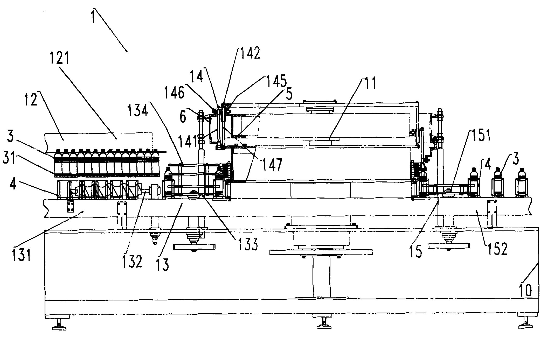
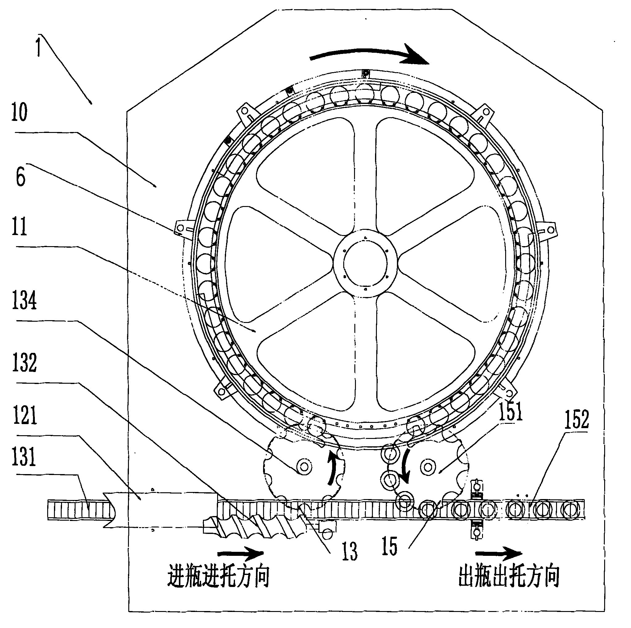
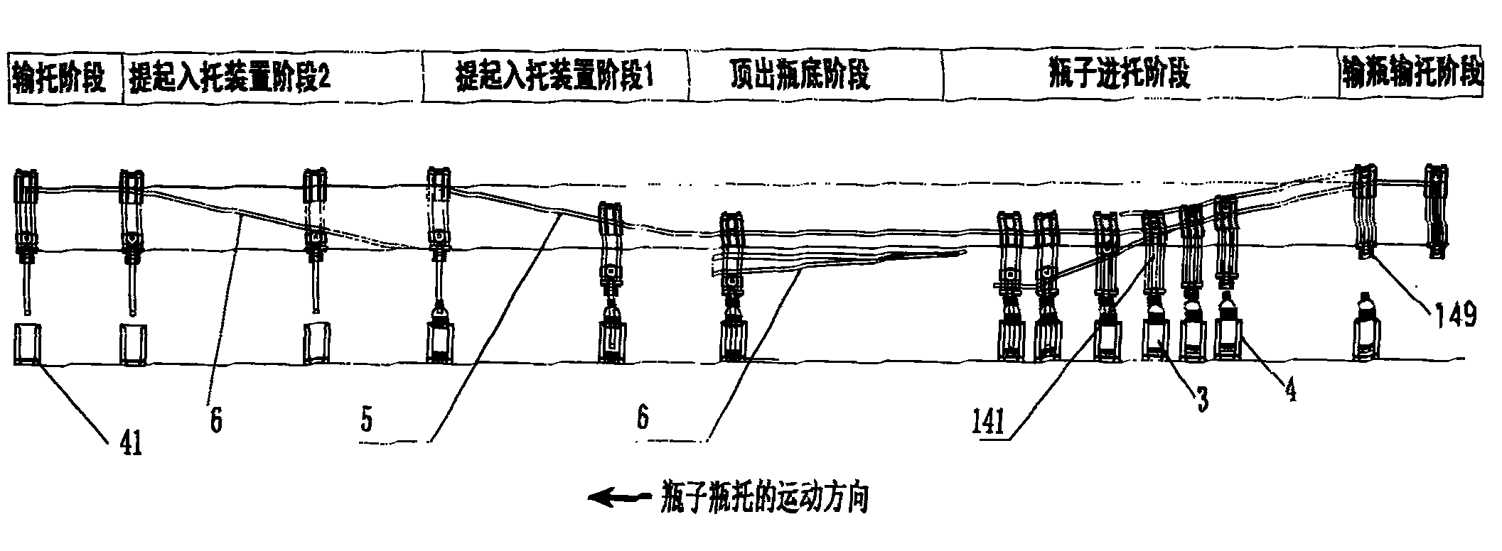
[0023] see Figure 1 to Figure 3 As shown, an energy-saving hot filling auxiliary equipment includes a tray-in machine 1 and an unloader 2 respectively arranged on the tray-in frame 10 and the tray-out frame 20, the tray-in machine 1 includes a tray-in machine rotating body 11, Transport the bottle holder 4 to the first star wheel transmission mechanism 13 in the rotating body 11 of the tray loading machine, and transport the bottle 3 with the inward bubbling 31 at the bottom of the bottle to the air feeding input bottle mechanism on the first star wheel transmission mechanism 13 12. The air-feeding input bottle mechanism 12 is arranged directly above the first conveying chain 131 of the first star wheel transmission mechanism 13, and the bottle 3 and the bottle holder 4 are placed on the first star wheel transmission mechanism 13 The top is in the position of upper and lower alignment; the inner cam 5 and the ejection device 14 for pressing the bottle 3 into the bottle holder...


PUM


Abstract

The invention discloses an energy-saving hot filling auxiliary device. In the device, a bottle holding machine comprises a rotating body of the bottle holding machine, a first star wheel transmission mechanism for conveying bottle holders into the rotating body of the bottle holding machine, and a pneumatically-conveyed bottle feeding mechanism for conveying bottles of which the bottoms have inward bubbles to the first star wheel transmission mechanism, wherein the pneumatically-conveyed bottle feeding mechanism is arranged above the first conveying chain of the first star wheel transmission mechanism, and the bottles and bottle holders are positioned on the first star wheel transmission mechanism at positions which are aligned up and down before entering the rotating body of the bottle holding machine; and an internal cam and a bottle holding ejecting device for pressing bottles into the bottle holders are arranged in the rotating body of the bottle holding machine, ejecting rods for ejecting the bottom bubbles of the bottles are arranged in bottle holding ejecting device, the internal cam is in rolling connection with the guide seat of the bottle holding ejecting device, an external cam is sleeved in the outer circle of the rotating body of the bottle holding machine, the external cam is supported by a plurality of upright posts so as to be fixed on a bottle holding machine frame, and the external cam is in rolling connection with the ejecting rods. The bottom bubbles instead of bottle contracted windows are adopted, so the weight of bottle blanks are further reduced and cost is reduced effectively.

Description

technical field [0001] The invention relates to an energy-saving hot filling auxiliary equipment, in particular to a tray loading and unloading device with a bottle tray. Background technique [0002] There are three filling methods for fruit and vegetable juice drinks currently on the market: 1. High temperature filling (85-92 degrees) 2. Medium temperature filling (below 70 degrees) 3. Aseptic filling (normal temperature). The same point in the way is that the packaging materials of beverages are all made of colorless and transparent PET materials. Because this material is an accessory in petroleum, its price is directly affected by the price of petroleum. The PET plastic bottle used in traditional high-temperature filling needs to ensure a certain thickness in order to withstand high temperature, and its gram weight ranges from 28 grams to 32 grams. The purpose of medium-temperature filling and aseptic filling is to reduce the weight of PET materials. Medium-temperature ...

Claims


Application Information

Patent Timeline
Patent Type & Authority Applications(China)
IPC IPC(8): B67C3/24
Inventor 陈刚黄威
Owner 广州俊升轻工机械有限公司
Learn More