3-D impeller of high-load centrifugal compressor

A technology of centrifugal compressor and ternary impeller, which is applied to pump components, mechanical equipment, machines/engines, etc., and can solve problems such as restricting advancement, friction loss, boundary layer separation loss, shear mixing loss, and insurance factor weight gain. , to achieve the effect of meeting the structural strength requirements, ensuring dynamic performance, and inhibiting the development of thickening

Inactive Publication Date: 2012-02-22
宋波 +1
View PDF0 Cites 0 Cited by
  • Summary
  • Abstract
  • Description
  • Claims
  • Application Information

AI Technical Summary

Problems solved by technology

[0004] (1) It is difficult to achieve the ideal design efficiency, that is, there is a large gap between the peak efficiency and the ideal level of the design limit;
[0005] (2) Even if it is close to the ideal peak efficiency, the effective working range of the impeller is not wide enough, which makes the performance of the compressor fly in the ointment;
[0006] (3) The limiting factors in the design of structural strength further restrict the pursuit of advanced aerodynamic performance. Even if the optimization of aerodynamic performance is improved, the structural design has to increase the insurance factor and increase the weight, which reduces the rotordynamic performance of the impeller.
Once this high load state is reached, the gas flow in the impeller will be pushed to the transonic range, and the organization and control of the flow will be more difficult, because at this time the loss of flow not only comes from the friction loss of the channel wall of the conventional subsonic design, Boundary layer separation loss, flow vortex loss, shear mixing loss due to flow inhomogeneity, and shock wave loss

Method used


Image

  • 3-D impeller of high-load centrifugal compressor
  • 3-D impeller of high-load centrifugal compressor
  • 3-D impeller of high-load centrifugal compressor

Examples


Embodiment Construction

[0023] The ternary impeller of the present invention will be described in detail below in conjunction with the accompanying drawings.

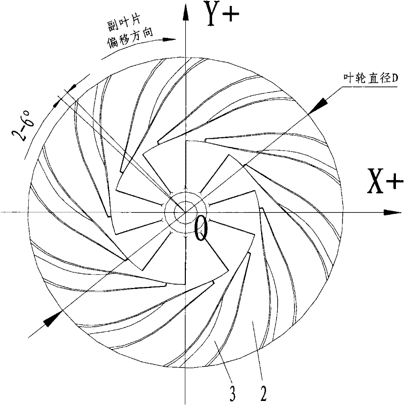
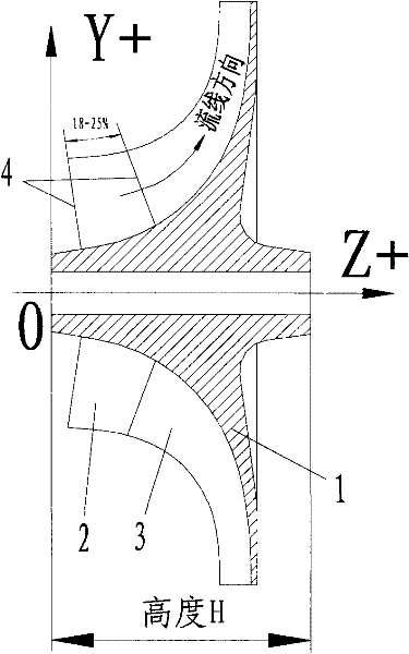
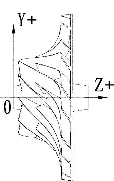
[0024] Such as Figure 1-3 As shown, the three-dimensional impeller of the high-load centrifugal compressor of the present invention includes a back plate 1 and three-dimensionally curved and twisted main blades 2 and auxiliary blades 3 whose surfaces are radially distributed around the center of the impeller, 10 main blades are uniformly distributed around the center of the impeller, and 10 The auxiliary blades are located between two main blades 2, and each auxiliary blade 3 is offset by 2-6° along the impeller rotation direction based on the circumferential center of the two main blades 2. At the position of 18-25% of the line direction, the front edges of the main and auxiliary blades are both arc-shaped, and the spatial shapes of the corresponding parts of the main and auxiliary blades are adapted.

[0025] The following is a specific sp...


PUM


Abstract

The invention discloses a 3-D impeller of a high-load centrifugal compressor, which comprises a back panel and blades which are radially distributed around the impeller center on the surface of the back panel, wherein the blades comprise a plurality of main blades and a plurality of auxiliary blades; the main blades are evenly distributed around the impeller center; the auxiliary blades are respectively positioned between every two main blades; each auxiliary blade deviates by 2-6 degrees in the rotation direction of the impeller by using the circumferential center of every two main blades asthe reference; the front edge of each auxiliary blade is positioned 18-25% of the grain direction of the main blade; the front edges of the main and auxiliary blades are both cambered; and the shapesof the spaces corresponding to the main and auxiliary blades match each other. The invention analyzes the technical line by using the all three-dimensional pneumatic design, and optimizes the flow channels and the pneumatic performance coherence of the complete machine to obtain the 3-D blades. The practice proves that the 3-D impeller ensures that the gradual loading process of gas flow in the channels are uniform, prevents flow from generating large vortices, and effectively controls the development, separation and shock loss at the boundary layer, thereby realizing high-efficiency flow of gas and achieving performance indexes of advanced international standards.

Description

technical field [0001] The invention relates to a ternary impeller of a centrifugal compressor, in particular to a ternary impeller of a high-load centrifugal compressor. Background technique [0002] As a necessary important industrial equipment, centrifugal compressors have always occupied an important place in the sustainable development of the national economy, and are an indispensable technical field and industry for the development of modern economic cycles. [0003] The research and development and manufacture of centrifuges are highly professional and technically challenging, and the disciplines involve aerodynamics, thermodynamics, fluid mechanics, heat transfer, solid mechanics, material mechanics, rotor dynamics, etc. Development level, such as materials, casting, machining, assembly, testing, electrical and electronics, control, system optimization design, engineering system management, etc., so the design and manufacturing technology is very difficult. Especial...

Claims


Application Information

Patent Timeline
Patent Type & Authority Patents(China)
IPC IPC(8): F04D29/28F04D29/30
Inventor 宋波雷先华
Owner 宋波
Why Eureka
Try Eureka