Clip

A clip and head technology, applied in the direction of threaded fasteners, thin plate connections, clothing, etc., can solve the problems of installation at a fixed position, clip insertion, fit and disengagement, etc., to achieve rapid and reliable installation, easy installation Effect

Active Publication Date: 2010-11-24
NIFCO INC
View PDF9 Cites 4 Cited by
  • Summary
  • Abstract
  • Description
  • Claims
  • Application Information

AI Technical Summary

Problems solved by technology

However, when the above-mentioned clip 51 is installed in a narrow place with an unnatural working posture, a part of the clip may be cut off and then inserted, or it may not be installed at a fixed position in a predetermined posture.
In addition, since the above-mentioned elastic legs 44, 45 cannot be centered skillfully, there is a problem that the fitting with the hole of the mounting member is disengaged.

Method used


Image

  • Clip
  • Clip
  • Clip

Examples


Embodiment

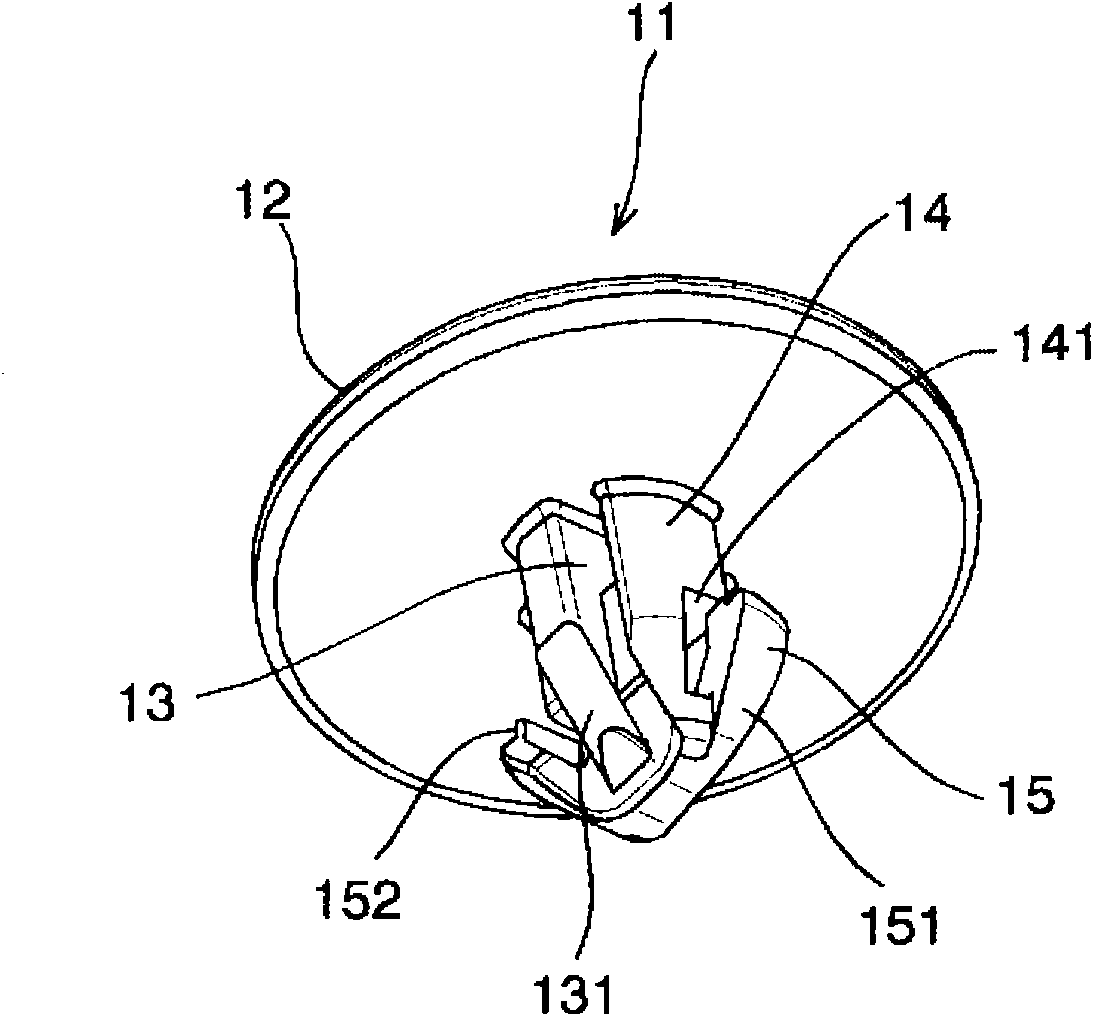
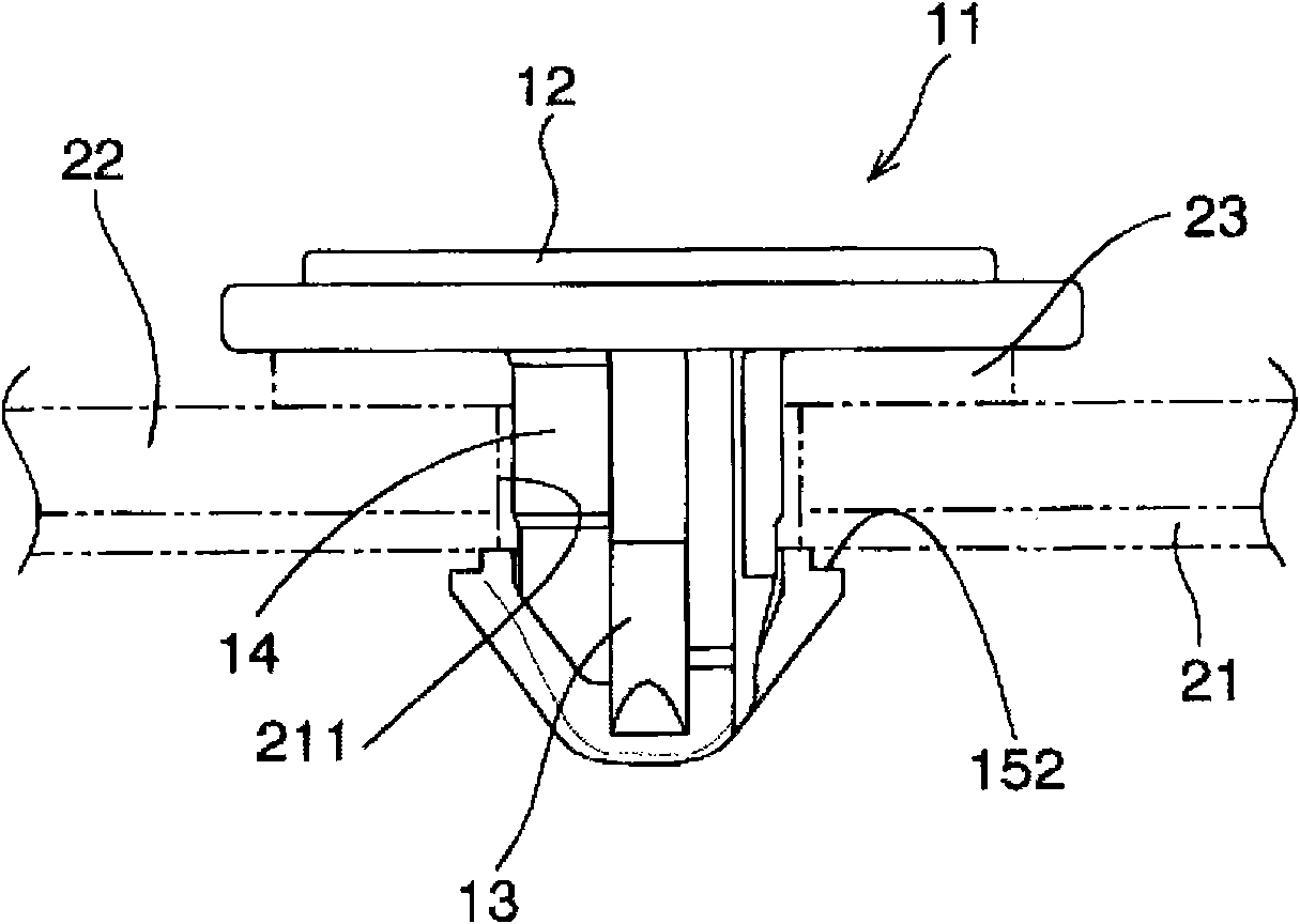
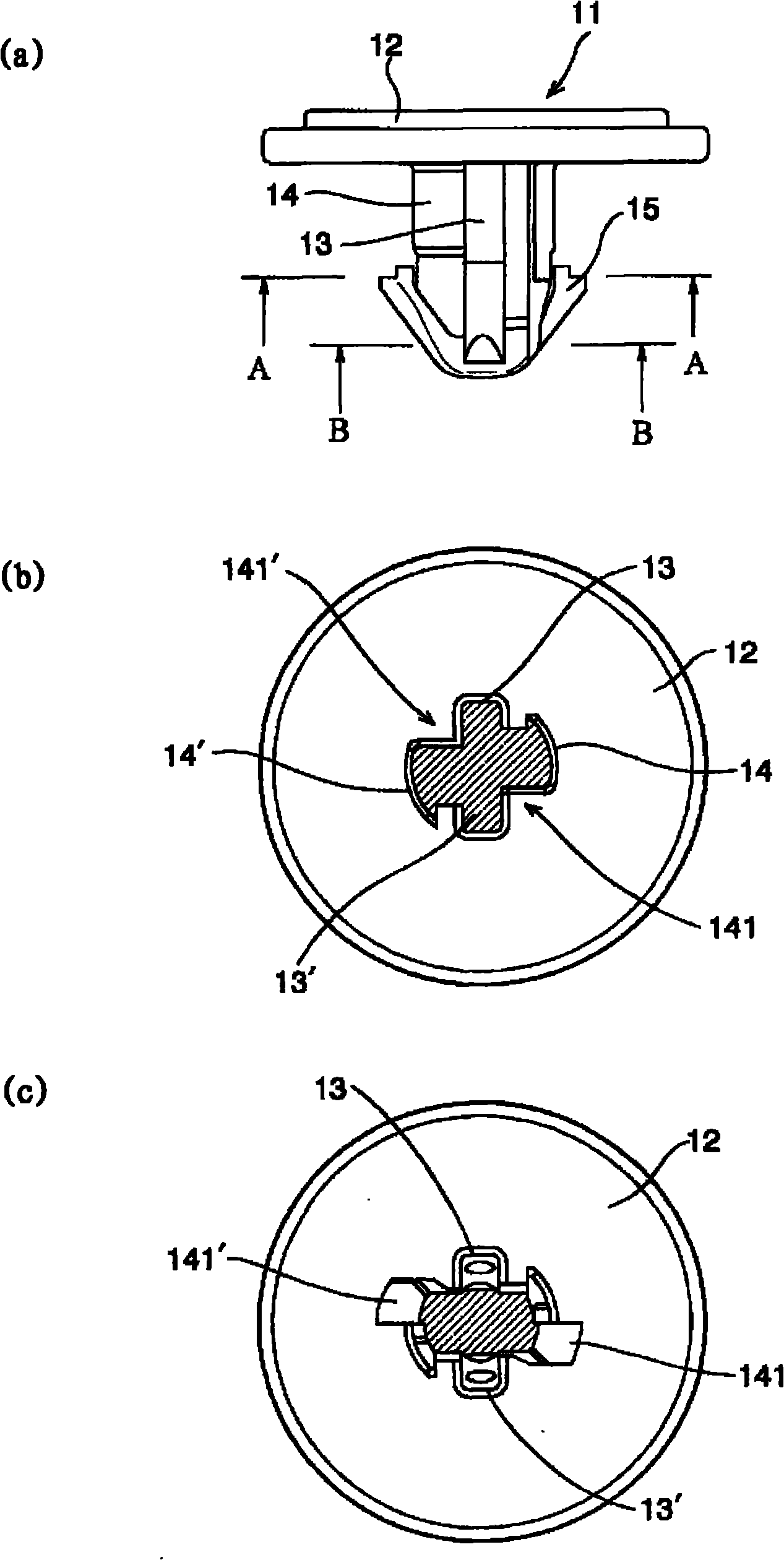
[0032] figure 1 It is a perspective view of the clip of the embodiment of the present invention. figure 2 It is a figure for explaining the state in which the clip which concerns on the embodiment of this invention is attached to the opening provided in the plate-shaped member. exist figure 1 and figure 2 Among them, the clip 11 is installed in the mounting holes 211 provided on the plate-shaped members 21 , 22 to be mounted on the mounted parts such as the fender inner panel and the fender. The clip 11 includes at least a head 12 , a central support 13 , an auxiliary support 14 , a V-shaped elastic leg 15 , a locking portion 152 and a space 141 . The head portion 12 has a shape locked to one surface of the plate-shaped member 21 via, for example, a packing 23 and a plate-shaped member 22 . The center pillar 13 has a shape that integrally protrudes downward from the head 12 and is inserted into the attachment hole 211 .

[0033] Like the central support 13 , the sub-p...


PUM


Abstract

The invention relates to a clip mounted on a mounting member by once through operation. The clip is provided with at least a head, a center support, an auxiliary support, elastic legs, engaging sections, and a cavity. The head has a shape capable of engaging with one surface of a member to which a mounting member is mounted. The center support is extended downward from the head and has a shape suitable to be inserted into a mounting hole. The auxiliary support is extended downward from the head in the same manner as the center support, and the base of the auxiliary support, said base being adapted to be inserted into the mounting hole, is formed integrally with both the head and the center support so as to be perpendicular to the center support. The pair of elastic legs, which expand in a V-shape, is interconnected with the tips of the center support and the auxiliary support and is formed in a shape which is turned back toward the head and the auxiliary support. The engaging sections which engage with the member to which a mounting member is mounted are provided to the tips of the elastic legs and are engaged with the mounting member or the other surface of the member to which the mounting member is mounted. The cavity is provided in the auxiliary support and is configured in such a manner that, when the elastic legs are deformed and inserted into the mounting hole, the cavity receives the deformed portions.

Description

technical field [0001] The present invention relates to a clip capable of mounting a mounted part by one operation. The present invention relates to a clip for installing, for example, a fender protector and a fender, and relates to a clip that improves installation workability during installation, can be accurately installed at a correct position, and is easy to install. Background technique [0002] Figure 4 It is a perspective view of a clip used to illustrate the prior art. exist Figure 4 Among them, the clip 41 is, for example, as described in Japanese Patent Application Laid-Open No. 62-156612, a first support 42 and a second support 43 hanging integrally from the unshown head, and from the above-mentioned first support 42. The first elastic leg 44 and the second elastic leg 45 extending integrally toward the head from the front end of the second strut 43 are arranged in a V shape. In addition, the first strut 42 , the second strut 43 , the first elastic leg 44 , a...

Claims


Application Information

Patent Timeline
Patent Type & Authority Applications(China)
IPC IPC(8): F16B19/00
CPCF16B21/086F16B5/0642Y10T24/309Y10T24/44026Y10T24/45105Y10T24/45262F16B5/10F16B19/00F16B21/04
Inventor 小岛亘长谷川隆洋
Owner NIFCO INC
Why Eureka
Try Eureka