Fast assembly fixture

A fixture and clamping technology, which is applied in the field of quick-fit fixtures, can solve problems such as limited application range, many components, and large tank volume, and achieve the effects of wide applicability, simple structure, and wide application

Inactive Publication Date: 2017-11-03
ANHUI KAICHENG ELECTRIC APPLIANCE CO LTD
View PDF0 Cites 1 Cited by
  • Summary
  • Abstract
  • Description
  • Claims
  • Application Information

AI Technical Summary

Problems solved by technology

[0003] However, in the actual production process, the production of metal tanks, especially large metal tanks such as reactors, due to their large volume and many components, often have problems such as docking difficulties and welding offsets during the assembly and welding of various components. At the same time, some of the existing fixtures used for pipe welding often have a large volume due to the large volume and weight of the tank, and it is difficult to connect and install during use, which limits the application range of this fixture
[0004] At the same time, in order to ensure the efficiency of welding, the existing pipe body welding fixtures usually place the pipe body horizontally on the fixture. In the actual application of this welding method, especially in the welding process of cylindrical tanks, welding The two parts of the tank usually rotate relative to each other during the welding process, resulting in uneven welds during the welding process, and problems such as partial welding and missing welding occur; while the vertical tank jig needs to be welded in the vertical direction during use. It is difficult to fix the body structure, especially the welding of special-shaped parts. Due to the irregularity of the welding part, it is difficult to fix the special-shaped parts. In addition, the welding of the tank body in the process of erecting the tank body is often accompanied by the difficulty of accurately aligning the center of the tank body structure. The problem occurs, causing the pipe body after welding to be uneven

Method used


Image

  • Fast assembly fixture

Examples


Embodiment Construction

[0017] In order to make the object, technical solution and advantages of the present invention clearer, the present invention will be described in detail below in conjunction with the accompanying drawings and specific embodiments.

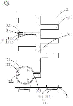
[0018] see figure 1 As shown, the present invention discloses a quick-release clamp 100 , including a base 1 , a support plate 2 fixedly mounted on the base 1 , and a clamp 3 connected and mounted on the support plate 2 .

[0019] The bottom of the base 1 is provided with a supporting foot 11 , and the supporting foot 11 includes a casing 111 and a supporting extension 112 accommodated in the casing 111 . The support extension 112 can be stretched out from the outer casing 111 to enhance the stability of the quick-installation clamp 100 and prevent the quick-installation clamp 100 from toppling after clamping the assembly.

[0020] The support plate 2 is fixedly installed on the base 1, and the support plate 2 is arranged in a plate shape. The m...


PUM


Abstract

The invention provides a quick-installation clamp, which includes a base, a support plate fixedly installed on the base, and a clamp connected and installed on the support plate. The lower end of the base is provided with support feet, wherein the vertical A clamp fixing rod is directly provided, and the clamp is provided with at least one, and is fixed on the clamp fixing rod; the clamp includes a connecting rod and a replaceable fixing part, and the connecting rod can be positioned on the clamp fixing rod in the up and down direction. Sliding, and can rotate between 0° and 180° on the first layer of the support plate; the support plate is provided with a supporting plate arranged in a disc shape between the fixture fixing rod and the connection position with the base. The quick-installation jig of the present invention can accurately fix the tank body to complete the welding; at the same time, the quick-installation jig is simple to assemble, has a fast combination installation speed, is convenient and simple to store, can greatly increase the combined welding speed of the tank body, and has a high applicability.

Description

technical field [0001] The invention relates to a fixing fixture, in particular to a quick-installing fixture that can quickly assemble and fix a tank body to be assembled. Background technique [0002] In the production process of existing metal tanks, each part of the tank structure is usually produced, and then assembled and welded to form a complete metal tank. [0003] However, in the actual production process, the production of metal tanks, especially large metal tanks such as reactors, due to their large volume and many components, often have problems such as docking difficulties and welding offsets during the assembly and welding of various components. , At the same time, some of the existing fixtures used for pipe welding often have a large volume due to the large volume and weight of the tank, and it is difficult to connect and install during use, which limits the application range of this fixture. [0004] At the same time, in order to ensure the efficiency of we...

Claims


Application Information

Patent Timeline
Patent Type & Authority Applications(China)
IPC IPC(8): B23K37/053
CPCB23K37/053
Inventor 刘开成
Owner ANHUI KAICHENG ELECTRIC APPLIANCE CO LTD
Why Eureka
Try Eureka