
Material flow device

A material flow and material technology, applied in furnaces, shaft furnaces, vertical furnaces, etc., can solve problems such as safety accidents, gas leakage, etc., achieve high safety, prevent gas leakage, and improve the safety factor

Active Publication Date: 2011-12-07
CISDI ENG CO LTD
View PDF0 Cites 0 Cited by
  • Summary
  • Abstract
  • Description
  • Claims
  • Application Information

AI Technical Summary

Problems solved by technology

On the top charging system and the bottom discharge system of the pellet furnace, it is necessary to install cutting equipment in order to overhaul and maintain the top and bottom equipment, and at the same time overhaul the key process main parts such as the shaft furnace body; On the other hand, it is necessary to pass high-pressure gas for sealing to prevent leakage of gas and cause safety accidents.

Method used


Image

  • Material flow device
  • Material flow device
  • Material flow device

Examples


Embodiment Construction

[0017] The present invention will be further described below in conjunction with the accompanying drawings and embodiments.

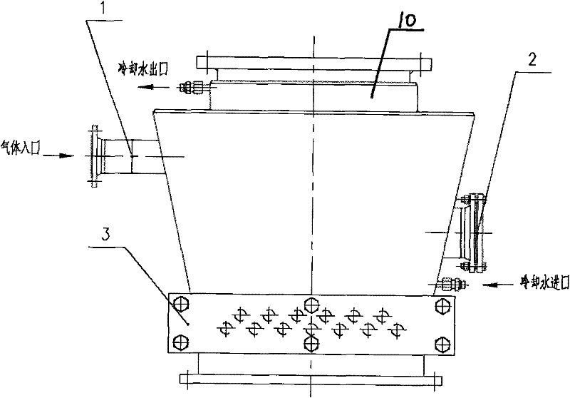
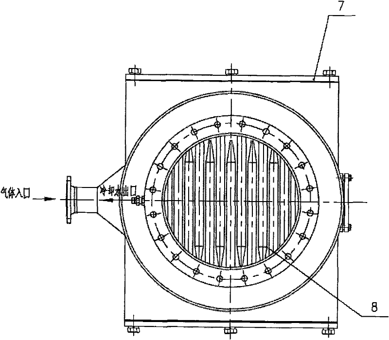
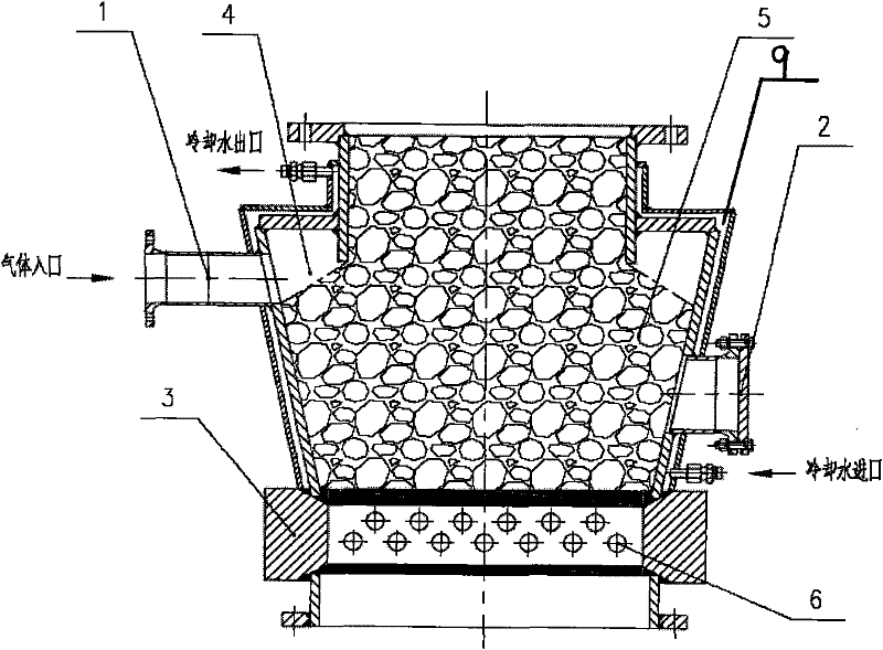
[0018] Such as figure 1 , figure 2 , image 3 as shown,

[0019] A material flow device, comprising a gas inlet pipe 1 arranged on the side of the gas seal section, the upper surface of the gas seal section is provided with a material inlet 10, the size of the material inlet 10 is smaller than the size of the upper surface of the gas seal section, the gas seal section The lower part of the sealing section is connected with a material cutting part 3 having a pinhole 6, and the two end faces of the material cutting part 3 are also provided with end face sealing covers 7. The device can be used in the normal pressure or low pressure reduction shaft furnace, the furnace top charging system or the furnace bottom discharge system. It plays a sealing role for the escape of reducing gas inside the equipment, and can also cut off the material during the equ...


PUM


Abstract

The invention discloses a material flow device. The device comprises a gas inlet pipe (1) which is arranged on the lateral side of a gas seal section, wherein the upper surface of the gas seal section is provided with a material inlet (10), and the size of the material inlet (10) is smaller than that of the upper surface of the gas seal section; the lower part of the gas seal section is connectedwith a material cutting part (3) with a pin hole (6); a steel pin (8) is inserted in the pin hole (6); and two end surfaces of the material cutting part (3) are provided with end surface sealing caps(7). The material flow device can cut materials and perform gas seal by spraying high pressure gas, and has simple structure and high safety.

Description

technical field [0001] The invention relates to a material flow device, in particular to a material flow device for a top charging system or bottom discharge system of a normal pressure or low pressure shaft furnace in the metallurgical industry. Background technique [0002] Coal gasification atmospheric pressure or low pressure reduction shaft furnace process mainly uses pellets as raw material to produce sponge iron. On the top charging system and the bottom discharge system of the pellet furnace, it is necessary to install cutting equipment in order to overhaul and maintain the top and bottom equipment, and at the same time overhaul the key process main parts such as the shaft furnace body; On the other hand, it is also necessary to pass high-pressure gas to seal, so as to prevent gas from leaking and causing safety accidents. [0003] At present, the gas seal equipment and cut-off equipment of the top and bottom of the direct reduction shaft furnace process respectivel...

Claims


Application Information

Patent Timeline
Patent Type & Authority Patents(China)
IPC IPC(8): F27B1/10F27B1/20F27B1/21F27B1/24C21B13/02
Inventor 蔡松伯王涛王蜀生赵渭康
Owner CISDI ENG CO LTD
Learn More