Microscope lens device with light guide function

A technology of microscope head and light function, applied in microscopes, optics, optical components, etc., can solve the problems of affecting the clarity of observation, the combination of light sources showing its three-dimensional shape, and the lack of suitable structure for general products.

Inactive Publication Date: 2010-11-24
I-SHOU UNIVERSITY
View PDF1 Cites 5 Cited by
  • Summary
  • Abstract
  • Description
  • Claims
  • Application Information

AI Technical Summary

Problems solved by technology

[0004] The image sensor 121 is electrically connected to an external image device (such as a computer, not shown in the figure) for the user to observe the enlarged image of the object under test 100 captured by the image sensor 121, but It should be noted that since the above-mentioned microscope lens device itself does not have any light source to illuminate the object 100 to be measured, the image definition at high magnifications is not good, and it can achieve Microscopic magnification is therefore limited
[0005] Therefore, see image 3 , 4 , the inventor of the present case has developed a hand-held microscopic identifier 2, the microlens device 21 used in it has a light-emitting element 211 itself, and then illuminates it when observing the object to be measured 100, but, although the above-mentioned The microlens device 21 of the hand-held microscopic identifier 2 has its own light-emitting element 211, but it can only provide an illumination source perpendicular to the object under test 100. Therefore, when the object under test 100 has reflective materials (such as conductive solder joints on the circuit board), which will directly reflect the vertical light source back to the microscope lens device 21, and form bright spots on the display screen, thereby affecting the clarity of observation
Furthermore, since the microlens device 21 is observed from a top view, if the object under test 100 (or its surface) is in a three-dimensional shape, the direct light source cannot clearly cooperate to show its three-dimensional shape, thereby causing the user The exact three-dimensional structure of the object under test 100 cannot be clearly identified during observation
[0006] This shows that above-mentioned existing microscope lens device obviously still has inconvenience and defect in structure and use, and urgently needs to be further improved
In order to solve the above-mentioned problems, the relevant manufacturers have tried their best to find a solution, but for a long time no suitable design has been developed, and the general product has no suitable structure to solve the above-mentioned problems. This is obviously the relevant industry. Urgent problem

Method used


Image

  • Microscope lens device with light guide function
  • Microscope lens device with light guide function
  • Microscope lens device with light guide function

Examples


Embodiment Construction

[0030]In order to further explain the technical means and effects that the present invention adopts to achieve the intended purpose of the invention, the specific implementation and structure of the microlens device with light guiding function proposed according to the present invention will be described below in conjunction with the accompanying drawings and preferred embodiments. , features and their effects are described in detail below.

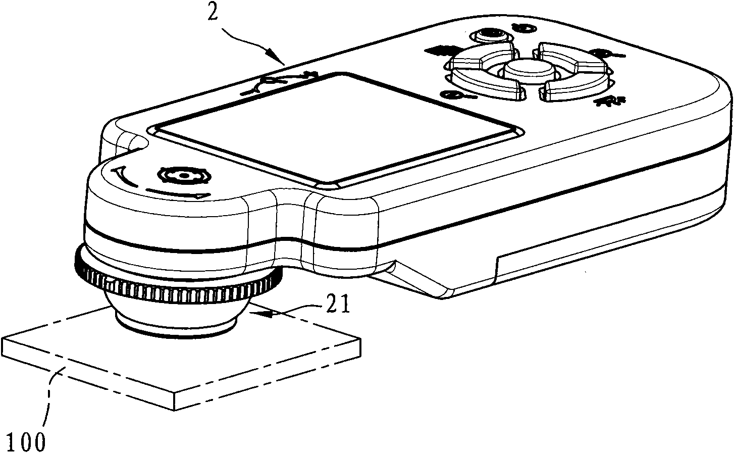
[0031] see Figure 5 , Figure 6 , a preferred embodiment of the microlens device with light guiding function of the present invention is used for microscopic magnification observation of an object to be measured 200, the microlens device includes: a base 3, an observation unit 4, a plurality of light emitting Component 5 , a sleeve unit 6 , a light guide cover 7 and a control unit 8 .

[0032] The observation unit 4 is disposed on the base 3 and used for amplifying the observed image of the object under test 200 . In this embodiment, ...


PUM


Abstract

The invention relates to a microscope lens device with a light guide function, which is used for performing magnification observation on an object to be measured. The microscope lens device comprises a base, an observation unit, a plurality of light-emitting components and a light guide shade, wherein the observation unit is integrated onto the base and used for magnifying the observed image of the object to be measured; the light-emitting components are arranged on the base around the observation unit and used for providing an illuminating light source; the light guide shade is provided with a light guide part and a through hole, the light guide part is arranged on the base and can guide light, and the through hole is formed on the light guide part; the illuminating light source of the light-emitting components inclinedly illuminates the object to be measured through the body, thereby preventing light rays from being directly reflected back to the observation unit to form bright spots on the display screen; and shadow generated by the inclined illumination can also be utilized to further observe the three-dimensional structure of the object to be measured.

Description

technical field [0001] The invention relates to a microlens device, in particular to a microlens device with light guiding function. Background technique [0002] Due to the development and progress of science and technology, many imitated products and currencies can be manufactured very well, and it is becoming more and more difficult to identify them from the real ones. However, it is very difficult to identify the authenticity by means of visual observation with the naked eye. Therefore, when doing business, it is easy to cause loss of property due to the difficulty of identifying products and currencies with the naked eye, or even because of small features. The misjudgment of the naked eye recognition of the graphics will cause unnecessary disputes. [0003] For this reason, there are a number of microscopic devices on the market for consumers to use for finer identification, see figure 1 , figure 2 , is the microlens device disclosed in U.S. Patent No. 7,102,817B1, ...

Claims


Application Information

Patent Timeline
Patent Type & Authority Applications(China)
IPC IPC(8): G02B21/02
Inventor 李彦杰蔡秀燕石名峰侯永鸿
Owner I-SHOU UNIVERSITY
Why Eureka
Try Eureka