A device for absorbing stray light

An absorption device and stray light technology, applied in optics, optical components, instruments, etc., can solve problems affecting the service life of optical components in the main optical path, polluting the clean environment of the beam pipeline, and cracking the surface of optical components, so as to reduce the risk of damage, miscellaneous Good astigmatism absorption effect, increase the effect of contact area

Active Publication Date: 2022-03-18
LASER FUSION RES CENT CHINA ACAD OF ENG PHYSICS
View PDF8 Cites 0 Cited by
  • Summary
  • Abstract
  • Description
  • Claims
  • Application Information

AI Technical Summary

Problems solved by technology

At present, commonly used stray light absorbers include wedge type, triangular pyramid type, louver type, and curved surface type. Stray light absorbers directly face high-flux stray light, and they face a greater risk of laser damage. Even if the absorber optics The damage threshold of the material is high, and long-term cumulative exposure to high-flux laser radiation will also cause cracks on the surface of optical components, dust and other particles, pollute the clean environment in the beam pipeline, and affect the service life of optical components in the main optical path

Method used


Image

  • A device for absorbing stray light
  • A device for absorbing stray light
  • A device for absorbing stray light

Examples


Embodiment 1

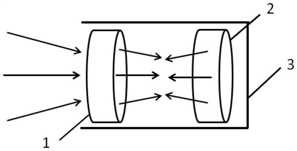
[0037] Such as figure 1 As shown, a stray light absorption device includes a lens 1, an absorber 2 and a peripheral pipe 3, wherein the lens 1 and the absorber 2 are sequentially arranged along the stray light transmission direction.

[0038] The lens 1 is used as a window of the stray light absorbing device to expand the incident stray light aperture. That is to say, the lens 1 is used to expand the incident stray light, which increases the contact area between the stray light and the absorber 2 and reduces the risk of laser flux damage. Specifically, the front surface of the lens 1 is coated with an anti-reflection film, which is used to transmit all the stray light into the stray light absorbing device as much as possible. At the same time, the curvature radius of the rear surface of the lens 1 is negative, which is used to expand the incident stray light aperture and reduce the laser damage load pressure of the absorber 2 . The lens 1 is made of an optical material with ...

Embodiment 2

[0046] Such as figure 1 As shown, the same parts of this embodiment and Embodiment 1 will not be repeated, and the difference is:

[0047] Lens 1 chooses fused silica, with a center thickness of 6mm and a clear aperture of 50mm×50mm. The front surface is coated with an anti-reflection coating. The transmittance within the clear aperture is better than 99.6%@351nm, and the radius of curvature of the rear surface is set to -100mm.

[0048] The absorber 2 is made of AB5 glass, the center thickness is 10mm, and the curvature radius of the front surface is -100mm. The lens 1 is placed with an inclination of 3° along the Y axis relative to the absorber 2 .

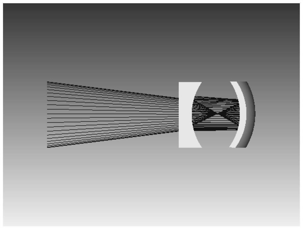
[0049] The focal distance of stray light is 400mm, the distance from the main point of stray light to lens 1 is 200mm, and the distance between lens 1 and absorber 2 is 100mm.

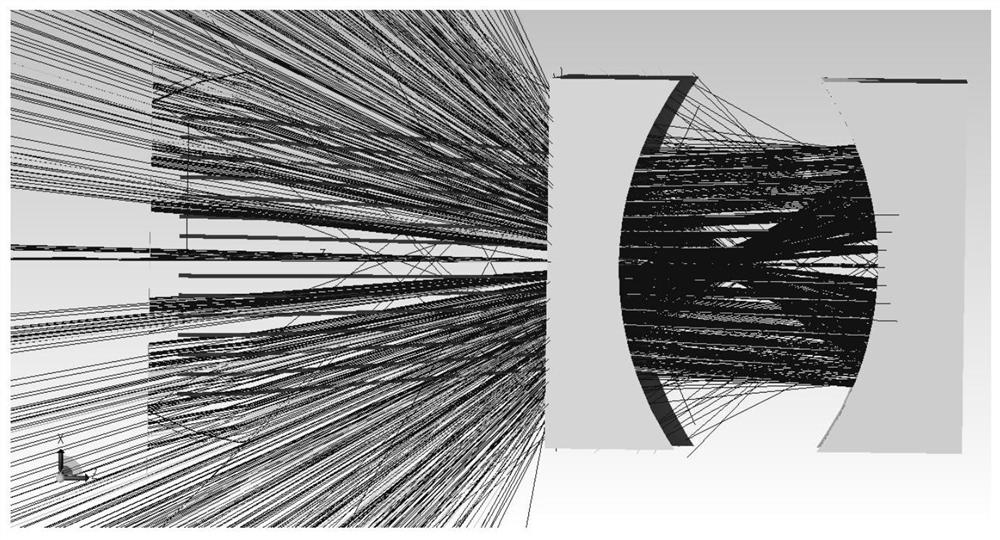
[0050] Based on the above optical parameters, the results of simulating the stray light absorption device based on the sequence mode of ZeMax ray trac...


PUM

PropertyMeasurementUnit
optical damage thresholdaaaaaaaaaa
thicknessaaaaaaaaaa

Abstract

The invention relates to a stray light absorbing device, which belongs to the technical field of high-power laser devices, and includes a lens, an absorber and a peripheral pipeline. The lens and the absorber are sequentially arranged along the stray light transmission direction, and the lens expands the incident stray light aperture. , the absorber absorbs part of the stray light, and reflects and converges the remaining stray light between it and the lens, and the stray light turns back between the absorber and the lens to consume energy. The inner wall of the invention can absorb stray light transmitted to its surface. The invention reduces the risk of stray light damage to optical elements, and at the same time, does not bring cleaning risks to the original optical path. The structure is simple and the design is reasonable, and the stray light absorption effect is good. Low production and processing costs.

Description

technical field [0001] The invention belongs to the technical field of high-power laser devices, and in particular relates to a stray light absorbing device. Background technique [0002] Large-scale high-power laser devices can output laser pulses with energy ranging from thousands of joules to tens of thousands of joules, and peak power up to terawatts or even exawatts. Due to the residual reflection of the surface film layer of the optical element, the laser pulse will generate complicated and uncontrollable stray light when it is transmitted and amplified in the optical link. High-flux stray light will damage optical components, degrade beam quality, and lead to a decrease in the life of the laser device, which seriously restricts the output performance of high-power laser devices. Therefore, how to control stray light has always been the focus of attention in the field of intense laser research and design. [0003] For the stray light in the form of divergence, the las...

Claims


Application Information

Patent Timeline
Patent Type & Authority Patents(China)
IPC IPC(8): G02B27/09G02B5/00
CPCG02B27/0927G02B27/0955G02B5/003
Inventor 宗兆玉赵军普李森梁樾熊迁龙蛟薛峤吴振海张君冯斌彭志涛胡东霞郑万国
Owner LASER FUSION RES CENT CHINA ACAD OF ENG PHYSICS
Why Eureka
Try Eureka