Gas and oil separator

A technology of oil-gas separator and oil-gas separation chamber, which is applied in the direction of machines/engines, engine components, mechanical equipment, etc., can solve the problems of oil-gas separation efficiency decline, burning, engine oil consumption increase, etc., to achieve better effect, Improve the effect and increase the effect of oil and gas separation rate

Active Publication Date: 2010-12-01
CHERY AUTOMOBILE CO LTD
View PDF7 Cites 31 Cited by
  • Summary
  • Abstract
  • Description
  • Claims
  • Application Information

AI Technical Summary

Problems solved by technology

[0002] At present, the oil and gas separators in the engine crankcase ventilation system have many structures, such as labyrinth, vortex, filter, etc. The principles and effects of separating oil and gas are also different, but these oil and gas separators have one thing in common, That is, when the gas in the crankcase passes through the oil-gas separator, only one oil-gas separation can be performed, and a structure of the oil-gas separator is usually only designed for oil and gas within a speed range, and the pressure in the crankcase is within a predetermined range When the speed of oil and gas is within the predetermined range, the effect of oil and gas separation can be expected, but if the pressure in the crankcase changes too much and exceeds the predetermined range, making the speed of oil and gas too low or too high, it will As a result, the efficiency of oil-air separation decreases, so that more oil will enter the intake manifold through the oil-air separator, and finally enter the combustion chamber to be burned, thus increasing the oil consumption of the engine

Method used


Image

  • Gas and oil separator
  • Gas and oil separator

Examples


Embodiment 1

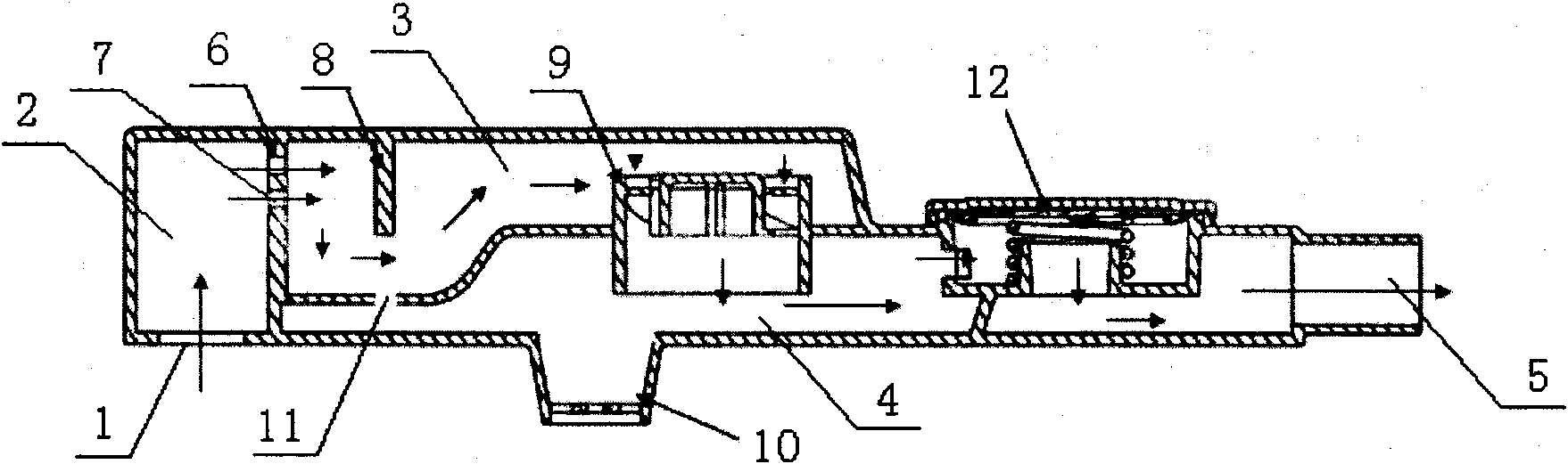
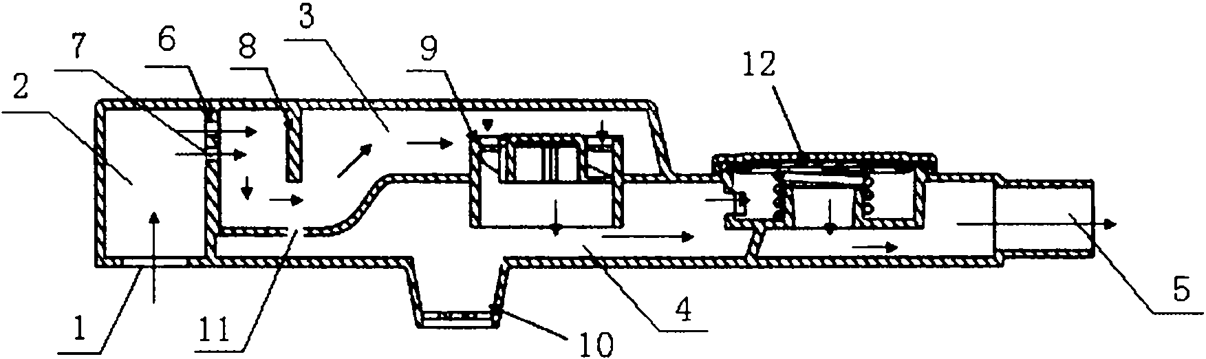
[0018] Such as figure 1 As shown, the oil-gas separator of this embodiment includes an air inlet 1, an air inlet 2 communicating with the air inlet 1, an oil-gas separation chamber 3, an air outlet 4, an air outlet 5, an air inlet 2 and an oil-air separation chamber 3 They are separated by a partition 6 with a through hole 7. A baffle 8 is arranged in the oil-gas separation chamber 3. The baffle 8 is located behind the partition 6 and faces the through hole 7 of the partition. The oil-gas separation chamber 3 passes through a The cylinder 9 with the spiral gas channel inside communicates with the air outlet 4 below, the cylinder 9 is vertically arranged behind the baffle 8, the bottom of the air outlet 4 is provided with an oil return tank 10, and the bottom plate of the oil-gas separation chamber below the baffle 8 A through hole 11 leading to the oil return tank 10 is provided, the air outlet 4 communicates with the air inlet of the PCV valve 12, the air outlet of the PCV va...


PUM


Abstract

The invention provides a gas and oil separator with good applicability and good gas and oil separating effect. The gas and oil separator comprises an air inlet, an air inlet passage communicated with the air inlet, a gas and oil separating cavity, an air outlet passage and an air outlet, wherein the air inlet passage and the gas and oil separating cavity are separated by a clapboard with a through hole; a baffle plate is arranged in the gas and oil separating cavity, is positioned behind the clapboard and faces the through hole of the clapboard; the gas and oil separating cavity is communicated with the air outlet passage below the gas and oil separating cavity through a cylinder in which a spiral air passage is formed; the cylinder is vertically arranged behind the baffle plate; an oil return groove is reserved at the bottom of the air outlet passage; a through hole communicated with the oil return groove is reserved on a gas and oil separating cavity bottom plate; and the air outlet passage is communicated with the air outlet through a PCV valve. Two types of gas and oil separating devices are arranged in the gas and oil separator and sequentially act to separate the gas and oil of the gas and oil separator for two times, so that the problem of poor effect of one-time separation of the traditional gas and oil separator is solved and the gas and oil separating effect is better.

Description

technical field [0001] The invention belongs to the technical field of automobile engines, in particular to an oil-gas separator for automobile engines. Background technique [0002] At present, the oil and gas separators in the engine crankcase ventilation system have many structures, such as labyrinth, vortex, filter, etc. The principles and effects of separating oil and gas are also different, but these oil and gas separators have one thing in common, That is, when the gas in the crankcase passes through the oil-gas separator, only one oil-gas separation can be performed, and a structure of the oil-gas separator is usually only designed for oil and gas within a speed range, and the pressure in the crankcase is within a predetermined range When the speed of oil and gas is within the predetermined range, the effect of oil and gas separation can be expected, but if the pressure in the crankcase changes too much and exceeds the predetermined range, making the speed of oil and...

Claims


Application Information

Patent Timeline
Patent Type & Authority Applications(China)
IPC IPC(8): F01M13/04
Inventor 徐勇王丽熊秋俊
Owner CHERY AUTOMOBILE CO LTD
Why Eureka
Try Eureka