Pneumatic parallel gate valve

A gate valve and gate technology, applied in sliding valves, balance valves, valve details, etc., can solve the problems of high-pressure pneumatic gate valve blanks, etc., and achieve the effects of good wear resistance, safe use, and convenient maintenance

Inactive Publication Date: 2010-12-01
CHENGDEJIANG DIAMOND OIL MASCH CO LTD
View PDF5 Cites 11 Cited by
  • Summary
  • Abstract
  • Description
  • Claims
  • Application Information

AI Technical Summary

Problems solved by technology

At present, the operation modes of parallel gate valves, especially the operation modes of high-pressure parallel ...

Method used


Image

  • Pneumatic parallel gate valve
  • Pneumatic parallel gate valve

Examples


Embodiment Construction

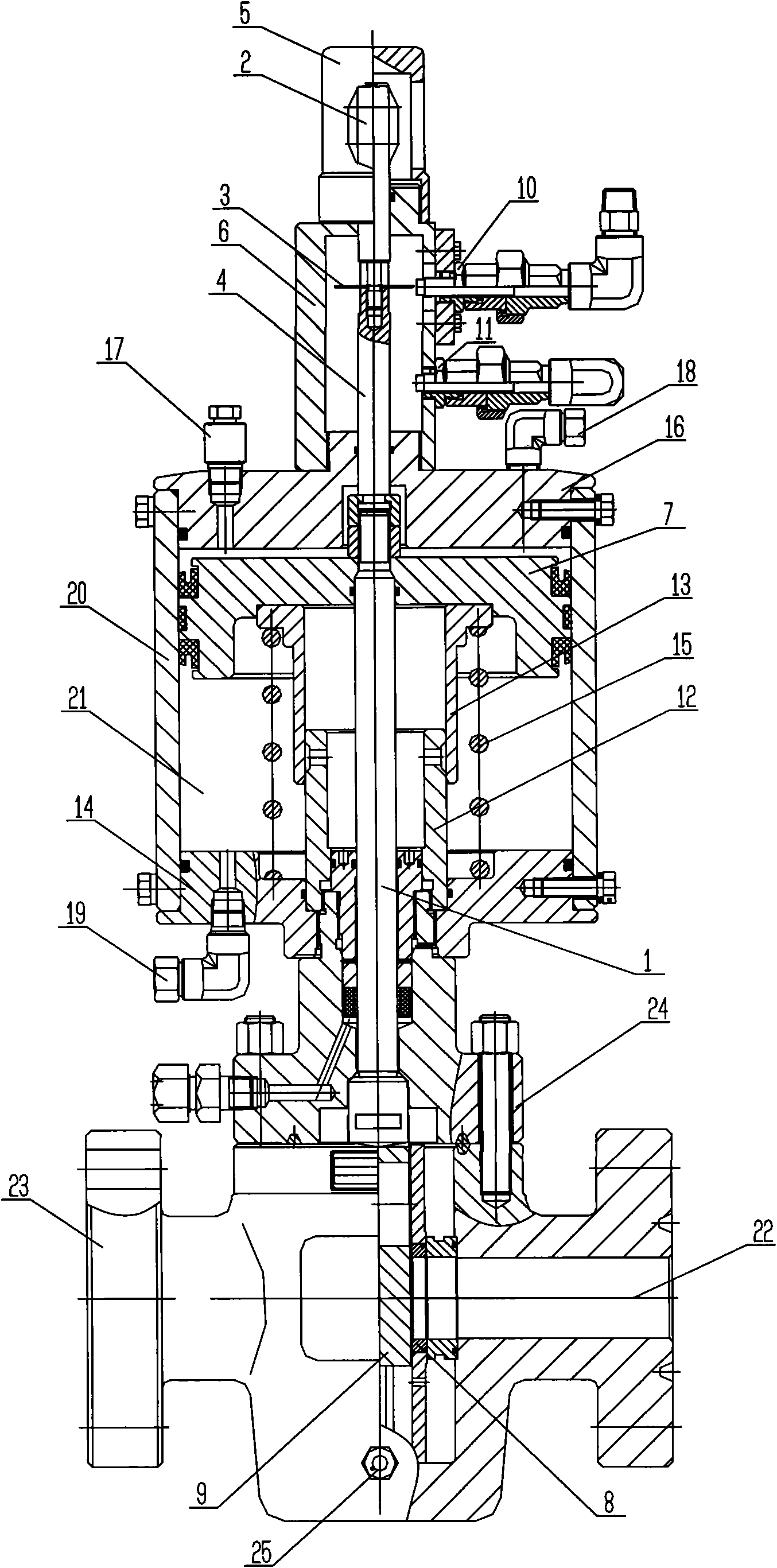
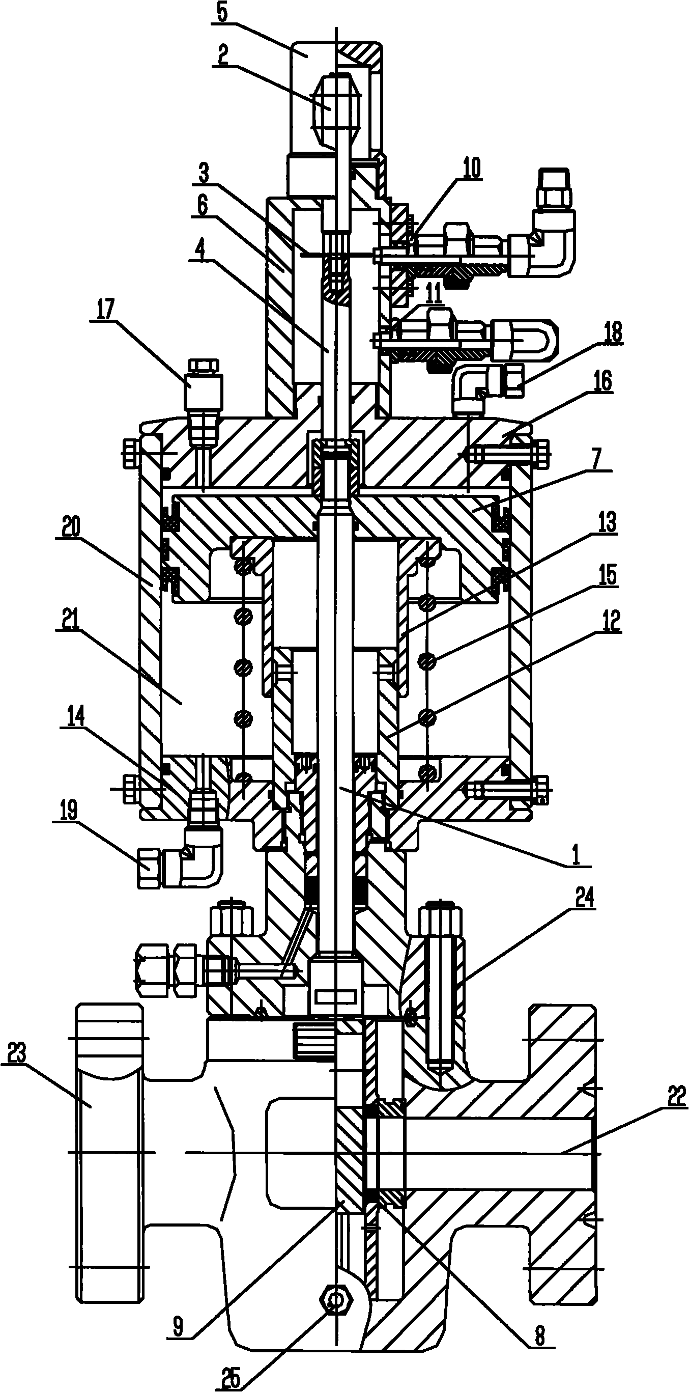
[0015] Below in conjunction with accompanying drawing, further illustrate the present invention through embodiment.

[0016] like figure 1 As shown, in the pneumatic parallel gate valve of the present invention, the upper part of the valve stem 1 braked by the piston 7 is sequentially connected with the display rod 2, the induction plate 3, and the connecting rod 4, and the display rod 2 is located in the display sheath 5 Inside, the induction plate 3 and the connecting rod 4 are located in the sheath 6, and the lower end of the valve stem 1 is connected with the gate plate 9 which is in sealing contact with the valve seat 8; Sensor 10 and lower sensor 11; the cylinder where piston 7 is located is located below the sheath 5, the lower end of the piston 7 is connected with a sliding sleeve 13 socketed with the guide sleeve 12, and the outer edge of the sliding sleeve 13 is connected with the lower cylinder cover 14 of the cylinder. The spring 15 arranged straight; the upper cy...


PUM


Abstract

The invention discloses a pneumatic parallel gate valve. An upper part of a valve rod braked by a piston is connected with a display rod, a sensing plate and a connection rod in turn; the display rod is positioned in a display jacket; the sensing plate and the connection rod are positioned in the sheath; a lower end of the valve rod is connected with a gate in close contact with a valve seat; upper and lower ends of the sensing plate are respectively provided with an upper sensor and a lower sensor for sensing the closing/opening of a valve; a cylinder where the piston is arranged is positioned below the jacket; a lower end of the piston is connected with a slide sleeve sleeved with a guide sleeve; a vertical spring is connected between an outer edge of the slide sleeve and a lower cylinder cover of the cylinder; an upper cylinder cover of the cylinder is provided with a safety valve and an upper sleeve chuck bent joint connected with an air source; the lower cylinder cover of the cylinder is provided with a lower sleeve chuck bent joint connected with the air source; the upper cylinder cover and the lower cylinder cover are connected through a cylinder sleeve; an air cavity of the cylinder is communicated with an oil line; and a valve cover connected with the valve is arranged below the cylinder. The pneumatic parallel gate valve has the advantages of safe use and convenient maintenance.

Description

technical field [0001] The invention relates to a valve, in particular to a pneumatically controlled parallel gate valve. Background technique [0002] Parallel gate valve is a kind of equipment widely used in oilfield operations, especially in drilling, testing and downhole operations. At present, the operation modes of parallel gate valves, especially the operation modes of high-pressure parallel gate valves above 34.5MPa, mainly include manual and hydraulic, but high-pressure pneumatic gate valves are still blank. Contents of the invention [0003] The purpose of the present invention is to provide a pneumatic parallel gate valve, which has the characteristics of safe use and convenient maintenance. [0004] In order to achieve the above purpose, the following technical solutions are adopted: [0005] A pneumatic parallel gate valve, the upper part of the valve stem braked by the piston is sequentially connected with the display rod, the induction plate, and the conne...

Claims


Application Information

Patent Timeline
IPC IPC(8): F16K3/02F16K31/122F16K17/00
Inventor 高世德胡彬彬王宏吉杨静
Owner CHENGDEJIANG DIAMOND OIL MASCH CO LTD
Why Eureka
Try Eureka