Multi-beam synthesizing method capable of supporting deflection scanning and T-type scanning

A technology of deflection scanning and synthesis method, which is applied in the directions of acoustic wave diagnosis, infrasonic wave diagnosis, and sound wave re-radiation, etc., which can solve the problems of not considering the support of deflection scanning, etc., and achieve the effect of simple implementation, simple control, and less resources used

Inactive Publication Date: 2013-03-27
SHENZHEN LANDWIND IND
View PDF6 Cites 0 Cited by
  • Summary
  • Abstract
  • Description
  • Claims
  • Application Information

AI Technical Summary

Problems solved by technology

However, this solution does not consider the support for deflection scanning. In addition, different probes need to switch the connection form of the circuit through two control signals C1 and C2 to support different types of probes.

Method used


Image

  • Multi-beam synthesizing method capable of supporting deflection scanning and T-type scanning
  • Multi-beam synthesizing method capable of supporting deflection scanning and T-type scanning
  • Multi-beam synthesizing method capable of supporting deflection scanning and T-type scanning

Examples


Embodiment Construction

[0044] Below according to accompanying drawing and embodiment the present invention will be described in further detail:

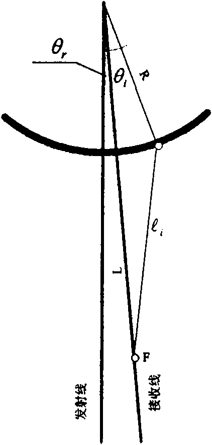
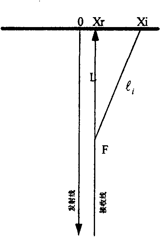
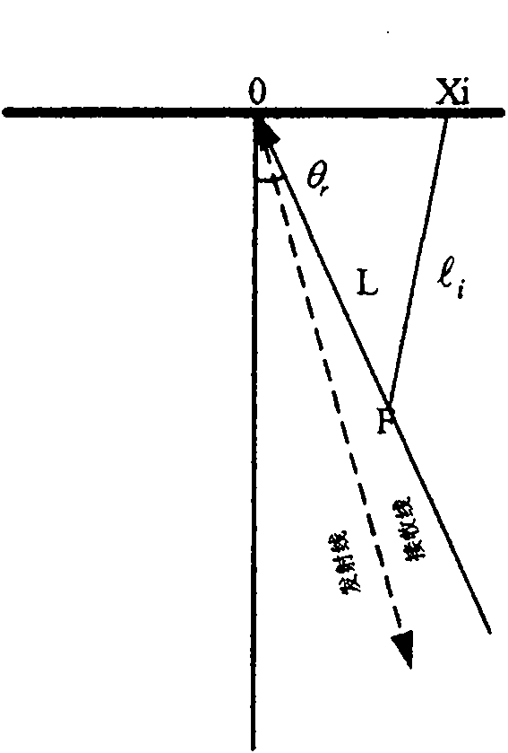
[0045] Depend on Figure 1 to Figure 6 It can be seen that the most important thing to calculate the focusing parameters is to calculate the sound path l from each array element to the focus i , the sound path calculation formulas of linear array probes, convex array probes and phased array probes in multi-beam scanning have been given in the patent application. The deflected scan can be regarded as a special case where the deflection angle θ is 0. according to Figure 4 The following sound path calculation formula for convex array with deflection scanning can be obtained:

[0046]

[0047] in d i = 2 R sin θ i - θ r 2 ...


PUM


Abstract

The invention discloses a multi-beam synthesizing method capable of supporting deflection scanning and T-type scanning. A real-time delay parameter calculation unit used by the method is a universal delay parameter calculating device which can be universally applied to a convex array probe, a linear array probe and a phased array probe. The method supports regular convex, linear and phased array multi-beam scanning modes, convex and linear array deflection scanning modes and linear, dummy and convex array scanning modes. Both a scanning angle (or position) and a deflection angle of a beam aredetermined by two input parameters.

Description

technical field [0001] The invention relates to a multi-beam synthesis method, in particular to a multi-beam synthesis method supporting deflection scanning and T-scanning, which can be applied to various types of probes. Background technique [0002] With the development of ultrasonic diagnostic equipment, more diversified scanning methods are required. For example, spatial composite imaging needs to change the scanning deflection direction on the basis of the original convex array or linear array scanning methods, and T-type (trapezoid) imaging needs to be realized with linear array probes. Imaginary scan, etc. In the patent that has been applied for "a multi-beam synthesis method and device based on real-time calculation and pipeline of delay parameters" (patent application number: 201010133657.7, US patent application number: 12 / 793,698), a real-time calculation and pipeline of delay parameters The multi-beam synthesis method (patent application number: 201010176005.7),...

Claims


Application Information

Patent Timeline
Patent Type & Authority Patents(China)
IPC IPC(8): G01S7/52G01S15/89A61B8/00
Inventor 孟国海
Owner SHENZHEN LANDWIND IND
Why Eureka
Try Eureka