Blind adaptive space-time array anti-interference method for navigation receiver

A navigation receiver, blind adaptive technology, applied in the field of anti-jamming, can solve problems such as large amount of calculation and error, and achieve the effect of reducing the amount of calculation

Inactive Publication Date: 2010-12-01
HARBIN INST OF TECH
View PDF1 Cites 21 Cited by
  • Summary
  • Abstract
  • Description
  • Claims
  • Application Information

AI Technical Summary

Problems solved by technology

[0013] In order to solve the problems of large amount of calculation and serious errors when the existing anti-interference technology suppresses broadband interference, the present invention proposes a blind adaptive space-time array anti-interference method for navigation receivers

Method used


Image

  • Blind adaptive space-time array anti-interference method for navigation receiver
  • Blind adaptive space-time array anti-interference method for navigation receiver
  • Blind adaptive space-time array anti-interference method for navigation receiver

Examples


specific Embodiment approach 1

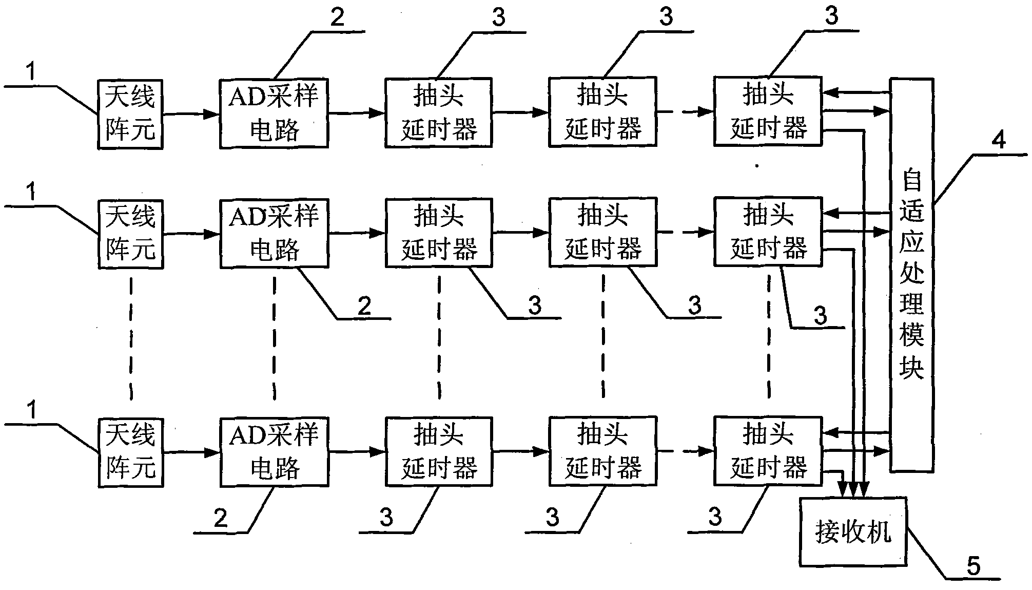
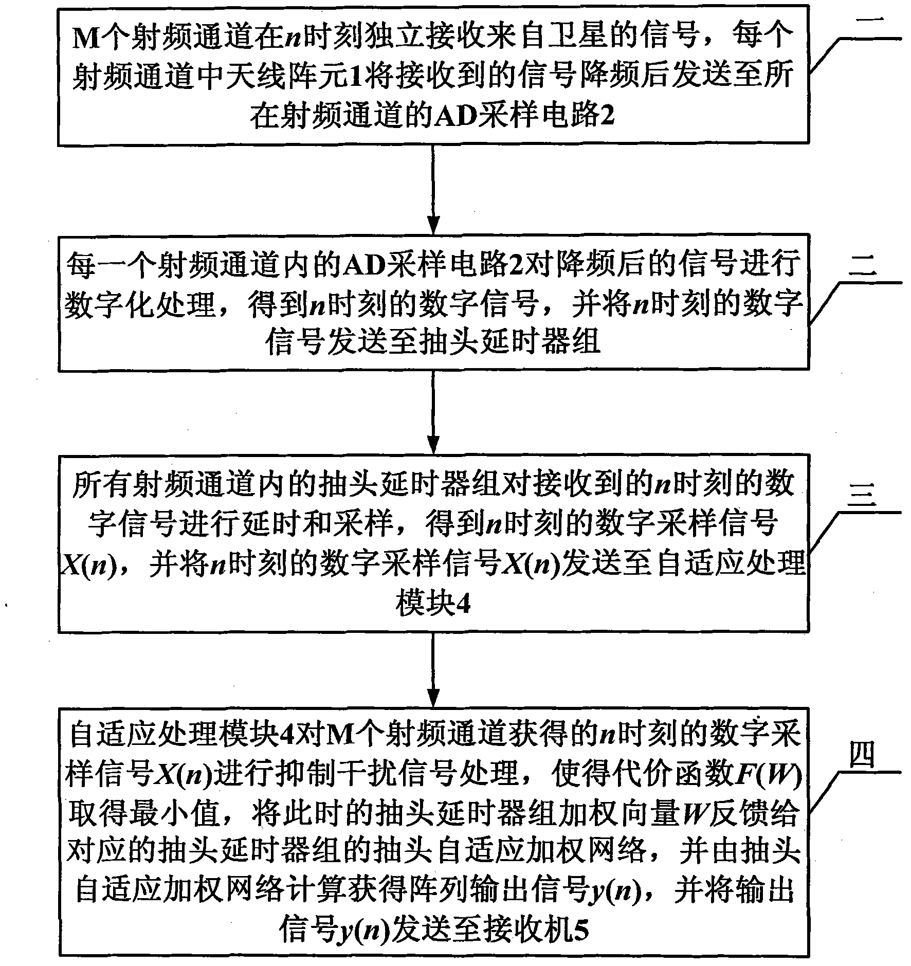
[0028] Specific implementation mode 1. Combination figure 1 and figure 2 Description of this embodiment, the navigation receiver blind adaptive space-time array anti-jamming method, it is completed based on the array antenna signal processing system, the array antenna signal processing system includes an adaptive processing module 4, a receiver 5 and M radio frequency channels, each radio frequency channel is composed of an antenna array element 1, an AD sampling circuit 2 and a tap delayer group, the tap delayer group is composed of N tap delayer 3 in series, and the M radio frequency channels The structure is the same, the signal output end of the antenna array element 1 in each radio frequency channel is connected with the signal input end of the AD sampling circuit 2, and the signal output end of the AD sampling circuit 2 is connected with the signal input end of the tap delayer group, the said The adaptive adjustment signal output end of the tap delayer group is connect...

specific Embodiment approach 2

[0036] Specific embodiment two, combine Figure 5 This embodiment is described. This embodiment is a further description of Embodiment 1. In Embodiment 1, the arrangement of antenna elements 1 is a circular array antenna array structure.

specific Embodiment approach 3

[0037] Specific embodiment three, combine Figure 5 Describe this embodiment, this embodiment is a further description of the second specific embodiment, the radius of the circular array antenna array structure is R, and M antenna elements 1 are provided, where M is an odd number, and one antenna element 1 is arranged at the center of the circle , M-1 antenna elements 1 are symmetrical oscillators arranged at equal intervals, and the distance from the antenna element 1 at the center of the circle is the radius R.


PUM


Abstract

The invention relates to a blind adaptive space-time array anti-interference method for a navigation receiver, relating to an anti-interference method for a navigation receiver. The invention solves the problems of large calculation amount and serious error when the traditional anti-interference technology is used for inhibiting broadband interference. The anti-interference method is realized on the basis of an array antenna signal processing system. The array antenna signal processing system comprises radio frequency channels, an adaptive processing module and a receiver, wherein each radio frequency channel is connected with the adaptive processing module, the adaptive processing module feeds back to the radio frequency channels, and the radio frequency channels are connected with the receiver. The method comprises the following specific steps of: performing AD (analog-digital) sampling to data by each radio frequency channel at medium frequency after frequency reduction; after sampling, passing a tapped delayer group; after delaying by each tapped delayer, sending signals to the adaptive processing module, and calculating weights by the module according to design; then, summing the weights of all taps to counteract the component of interference signals; and finally, outputting to the receiver for subsequent processing. The anti-interference method is applicable to the anti-interference field of navigation receivers.

Description

technical field [0001] The invention relates to an anti-jamming method for a navigation receiver. Background technique [0002] GNSS (Global Navigation Satellite System, GNSS) is not only widely used in roads, railways, shipping, telecommunications , public security, fire protection and other departments and industries, and can be used in military fields such as spacecraft flight, space station docking, shooting range measurement and control, aviation, military reconnaissance, battlefield individual combat systems, smart weapons, smart bombs, etc. GPS in the United States, Galileo in Europe, GLONASS in Russia and BD in China are all types of GNSS. [0003] Modern warfare is information warfare under nuclear deterrence, and information and knowledge will become the dominant factors in future warfare. Real-time precise position, velocity, time and attitude (PVTA) information plays an important role in modern warfare. Among the systems that can provide PVTA information, ther...

Claims


Application Information

Patent Timeline
Patent Type & Authority Applications(China)
IPC IPC(8): G01S19/21
Inventor 刘恩晓孟维晓方睿史雨薇
Owner HARBIN INST OF TECH
Why Eureka
Try Eureka