Auxiliary pressure relief valve

A technology for pressure relief valves and slide valves, which is applied in the direction of slide valves, valve details, safety valves, etc., and can solve problems such as incomplete pressure relief

Active Publication Date: 2010-12-08
AUTOL TECH
View PDF6 Cites 11 Cited by
  • Summary
  • Abstract
  • Description
  • Claims
  • Application Information

AI Technical Summary

Problems solved by technology

[0003] The purpose of the present invention is to provide an auxiliary pressure relief valve to solve the problem of incomplete pressure relief in the existing volumetric lubrication system

Method used


Image

  • Auxiliary pressure relief valve
  • Auxiliary pressure relief valve
  • Auxiliary pressure relief valve

Examples


Embodiment Construction

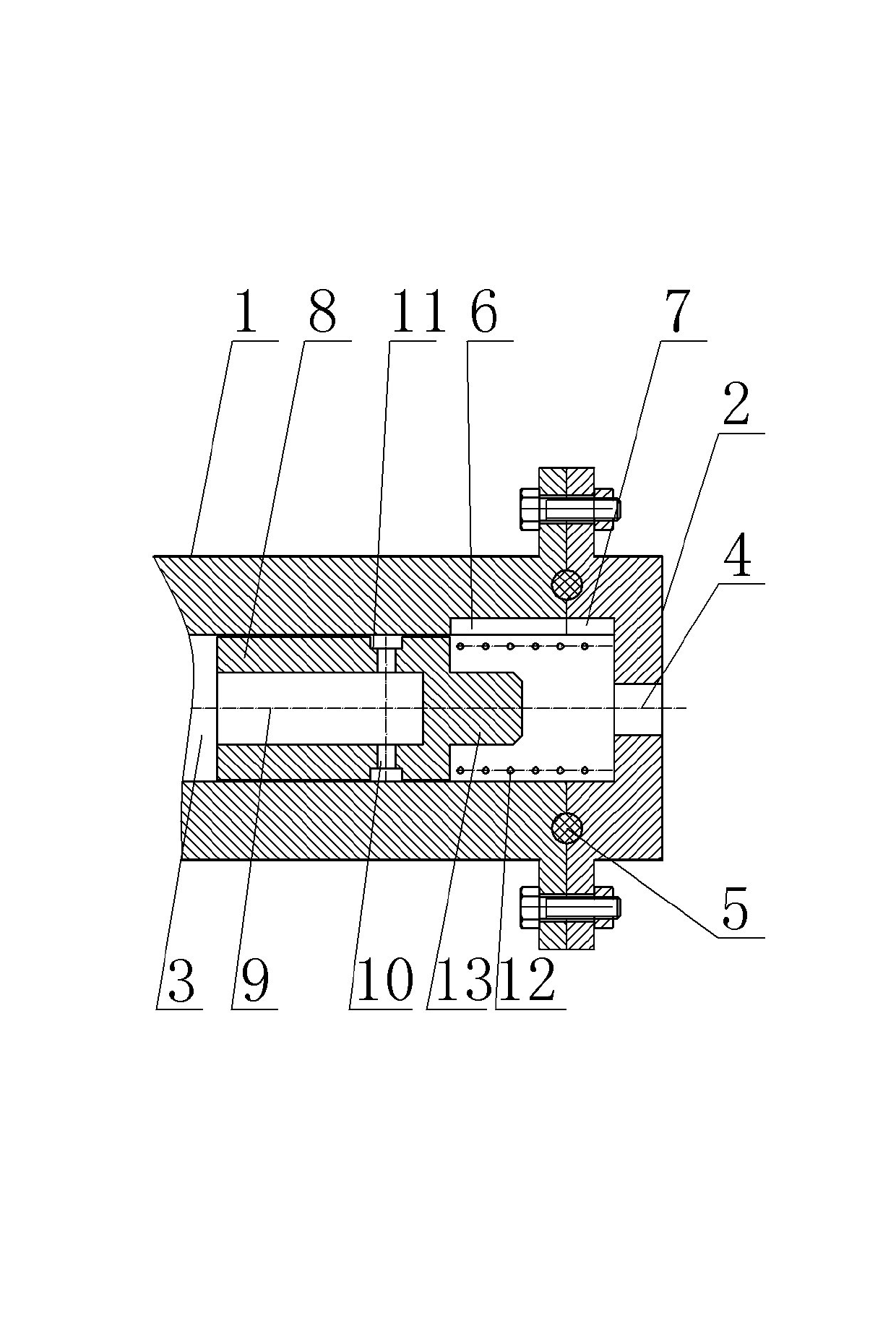
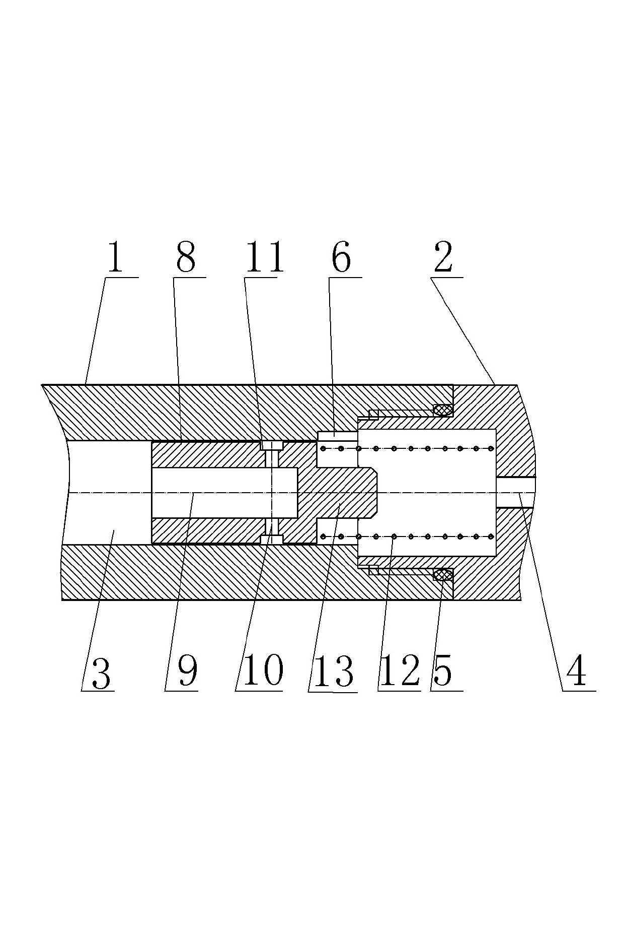
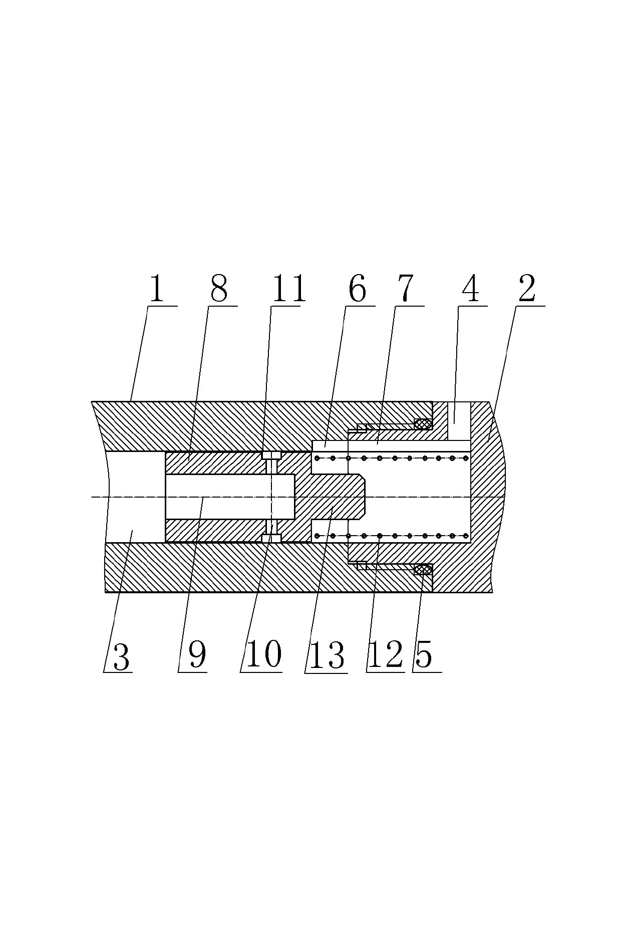
[0019] Embodiment 1 of the auxiliary pressure relief valve of the present invention, such as figure 1 As shown, the slide valve body includes a slide valve body body 1 and a matching body 2. The slide valve body body 1 is a cylindrical structure with two ends open. One end of the slide valve body body 1 has an oil inlet 3, and the other end is connected to the matching body 2 Fixed and sealed connection, the spool body body 1 has an oil outlet hole 4 through the inner and outer walls in the circumferential direction near the end of the fitting body 2, the fitting body 2 is a cylindrical structure with one end open, the opening end of the fitting body 2 and the slide valve body The main body 1 is screwed, and a sealing ring 5 is sandwiched between the mating body 2 and the spool body body 1. The inner wall surface of the end of the spool body body 1 close to the mating body 2 has a first axial length through its corresponding end face. Groove 6, the first long groove 6 communic...


PUM


Abstract

The invention relates to an auxiliary pressure relief valve which comprises a sliding valve body and a sliding valve core which is arranged in the valve body in a sliding way, wherein the sliding valve body is of a cylindrical structure with one open end, one end face of the sliding valve core, which is far away from the closed end of the valve body, is provided with an axial blind hole, the peripheral surface of the sliding valve body is provided with an oil outlet which is communicated with the axial blind hole, the sliding valve body is provided with an oil outlet channel which is communicated with the oil outlet after the sliding valve core bears an upstream oil-pumping pressure and is displaced; a pressure relief spring which is used for returning the sliding valve core after the upstream oil-pumping of the sliding valve core is completed is arranged between one end of the sliding valve core, which is far away from the axial blind hole, and the closed end of the sliding valve body; a sealing pressure relief route for downstream pressure relief during the returning process of the sliding valve core exists between the oil outlet and the inner wall face of the sliding valve body; and the peripheral face of the sliding valve core, which corresponds to the oil outlet, is provided with a peripheral ring groove, and / or the inner wall face of the sliding valve body, which corresponds to the oil outlet channel and matches with the oil outlet, is provided with a peripheral ring groove.

Description

technical field [0001] The invention relates to the technical field of centralized lubrication, in particular to an auxiliary pressure relief valve. Background technique [0002] Volumetric centralized lubrication technology has been widely used in the field of lubrication technology due to its high reliability, precise oil discharge, low cost and low pressure requirements for lubrication pumps and pipeline systems. In order to ensure the normal operation of the distributor of volume pressure relief centralized lubrication, this technology requires that after the operation of the lubricating pump, the oil pressure near the oil separator group in the main oil circuit must be completely removed, so that the oil separator can supply oil to each lubrication point. Therefore, in this structure, an unloading valve is installed at the oil outlet of the pump in the fuel tank. After the system stops running, the pressure relief port will be opened automatically, and the oil in the ma...

Claims


Application Information

Patent Timeline
Patent Type & Authority Applications(China)
IPC IPC(8): F16N23/00F16K3/00F16K17/04F16K27/04
Inventor 赵大平和兆乐王德全
Owner AUTOL TECH
Why Eureka
Try Eureka