Knocking detection device for internal combustion engine

A detection device, internal combustion engine technology, applied in the direction of internal combustion engine testing, measuring devices, engine testing, etc.

Active Publication Date: 2010-12-08
HONDA MOTOR CO LTD
View PDF3 Cites 6 Cited by
  • Summary
  • Abstract
  • Description
  • Claims
  • Application Information

AI Technical Summary

Problems solved by technology

In this way, when the influence of the seating noise is shown in the output signal of the knock sensor, since a specific frequency component is shown with the same level of intensity as when knocking occurs, there may be an error in determining that there is no knocking. possibility of knocking

Method used


Image

  • Knocking detection device for internal combustion engine
  • Knocking detection device for internal combustion engine
  • Knocking detection device for internal combustion engine

Examples


no. 1 Embodiment approach

[0058] figure 1 It is an overall configuration diagram of an internal combustion engine (hereinafter referred to as "engine") and its control device according to an embodiment of the present invention. For example, a throttle valve 3 is disposed in the middle of an intake pipe 2 of a four-cylinder engine 1 . The throttle valve 3 is connected to a throttle opening sensor 4 that detects a throttle opening TH, and a detection signal from the sensor 4 is supplied to an electronic control unit (hereinafter referred to as “ECU”) 5 .

[0059] For each cylinder, a fuel injection valve 6 is provided slightly upstream of an unillustrated intake valve located between the engine 1 and the throttle valve 3 and in the intake pipe 2, and each injection valve is connected to an unillustrated intake valve. The fuel pump is connected and electrically connected to the ECU 5 , and the opening timing of the fuel injection valve 6 is controlled based on a signal from the ECU 5 . A spark plug 7 is...

no. 2 Embodiment approach

[0137] In this embodiment, the knock determination processing in the first embodiment ( Figure 8 ) changed to Figure 18 treatment shown. Except for the points described below, it is the same as the first embodiment.

[0138] exist Figure 18 In the processing shown, first, noise removal processing is performed on the intensity parameter KMAP before binarization, and the corrected intensity parameter JKMAPI is calculated (step S12a), the corrected intensity parameter JKMAPI is binarized, and the corrected binarized intensity parameter is calculated JKMAP (step S11b).

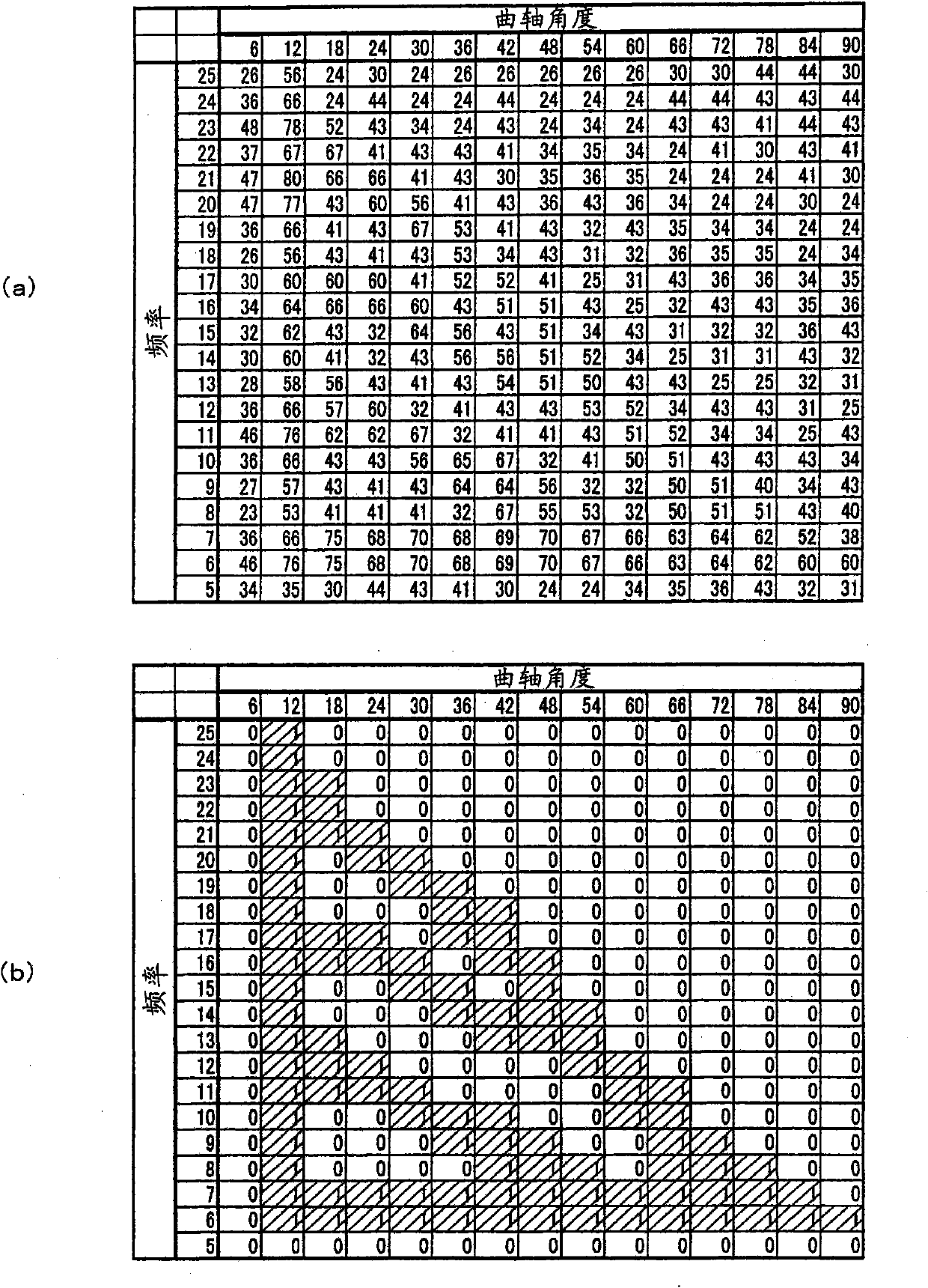
[0139] Figure 19 (a) shows an example of the frequency spectrum sequence map in this embodiment, Figure 19 (b) is a figure which shows an example of the noise map in this embodiment, and the noise learning value which is not binarized is set. The noise removal process is done by starting from Figure 19 Subtract from each map value of the frequency spectrum timing map of (a) Figure 19 (b) for the noi...

no. 3 Embodiment approach

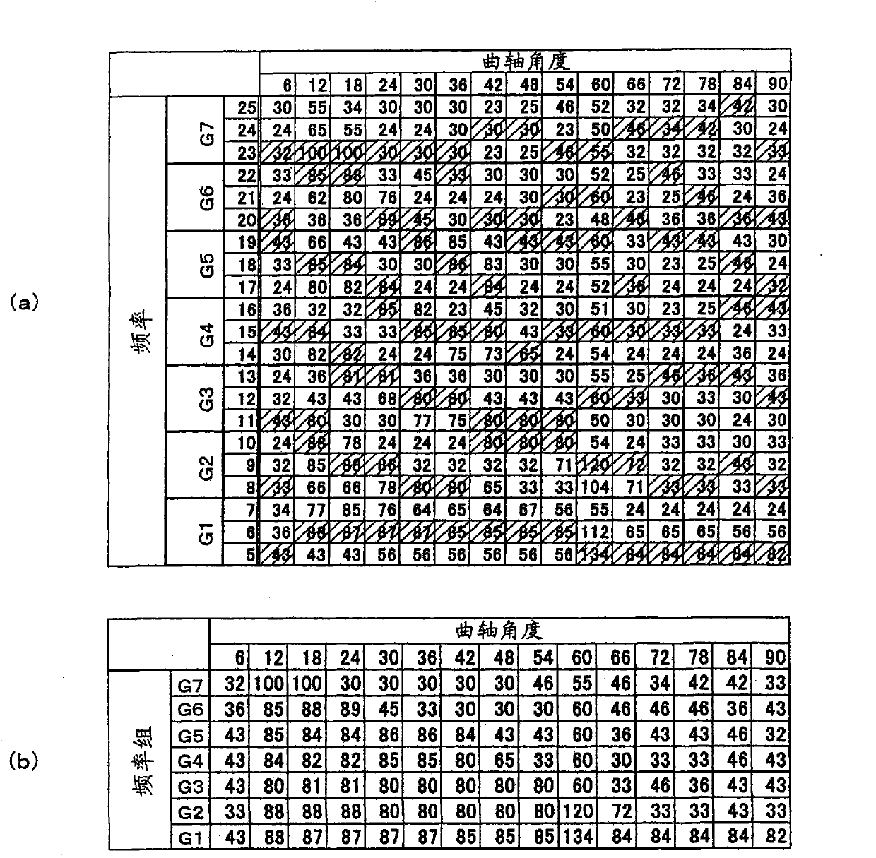
[0160] This embodiment is configured by dividing (grouping) 21 frequencies from 5 kHz to 25 kHz into seven frequency groups G1 to G7 consisting of three frequencies, and grouping the representative value of the intensity parameter KMAP corresponding to one sampling timing. The strength parameter GKMAP is set to the maximum value within the frequency group. By performing grouping in this way at the beginning, the number of data to be subjected to noise removal processing, binarization processing, and fitness rate calculation processing is reduced to 1 / 3, and the calculation load can be greatly reduced. In addition, it is the same as the second embodiment except for the points described below.

[0161] Figure 25 is a diagram for explaining grouping. Such as Figure 25 As shown in (a), frequencies 5kHz, 6kHz, 7kHz correspond to frequency group G1; frequencies 8kHz, 9kHz, 10kHz correspond to frequency group G2; frequencies 11kHz, 12kHz, 13kHz correspond to frequency group G3; fr...


PUM


Abstract

Provided is a knocking detector of an internal combustion engine which can correctly judge whether knocking occurs or not based on the frequency components of an output signal of a knock sensor. Frequency component analysis is performed on the output signal of the knock sensor at predetermined crank angle intervals, and the intensities of a plurality of frequency components obtained by the frequency component analysis are stored as time series data. The time series data of the frequency component intensities is converted into a binary form, and it is judged whether knocking occurs or not based on the binary time series data.

Description

technical field [0001] The invention relates to a knock detection device of an internal combustion engine, in particular to a knock detection device of an internal combustion engine which judges whether there is knock or not according to the frequency component of the output signal of a knock sensor. Background technique [0002] Patent Document 1 discloses a knock detection device that obtains a plurality of resonance frequency components contained in an output signal of a knock sensor, calculates a knock index based on the plurality of resonance frequency components, and combines the knock index and The predetermined value is compared to determine whether there is knocking. [0003] Patent Document 1: Japanese Patent No. 2684611 [0004] In the method shown in Patent Document 1, the intensities of frequency components corresponding to, for example, 16 frequencies are calculated by fast Fourier transform, five frequency components with high intensities are selected, and ea...

Claims


Application Information

Patent Timeline
Patent Type & Authority Applications(China)
IPC IPC(8): F02D45/00G01M15/06G01M15/12
CPCF02D2041/288F02D2250/14G01L23/221F02D35/027G01M15/12G01M15/042
Inventor 小松弘崇高木治郎仓内淳史义煎将之广田和彦北村夏子明本禧洙
Owner HONDA MOTOR CO LTD
Why Eureka
Try Eureka