Control valve trim and seal

A technology of sealing rings and sealing bands, which is applied in the field of control valves and can solve problems such as product quality impact and unintentional leakage

Active Publication Date: 2010-12-08
FISHER CONTROLS INT LLC
View PDF1 Cites 8 Cited by
  • Summary
  • Abstract
  • Description
  • Claims
  • Application Information

AI Technical Summary

Problems solved by technology

If and when these properties are compromised, the quality of the final product will suffer
One reason why the stated properties may be compromised is inadvertent leaks in the process

Method used


Image

  • Control valve trim and seal
  • Control valve trim and seal
  • Control valve trim and seal

Examples


Embodiment Construction

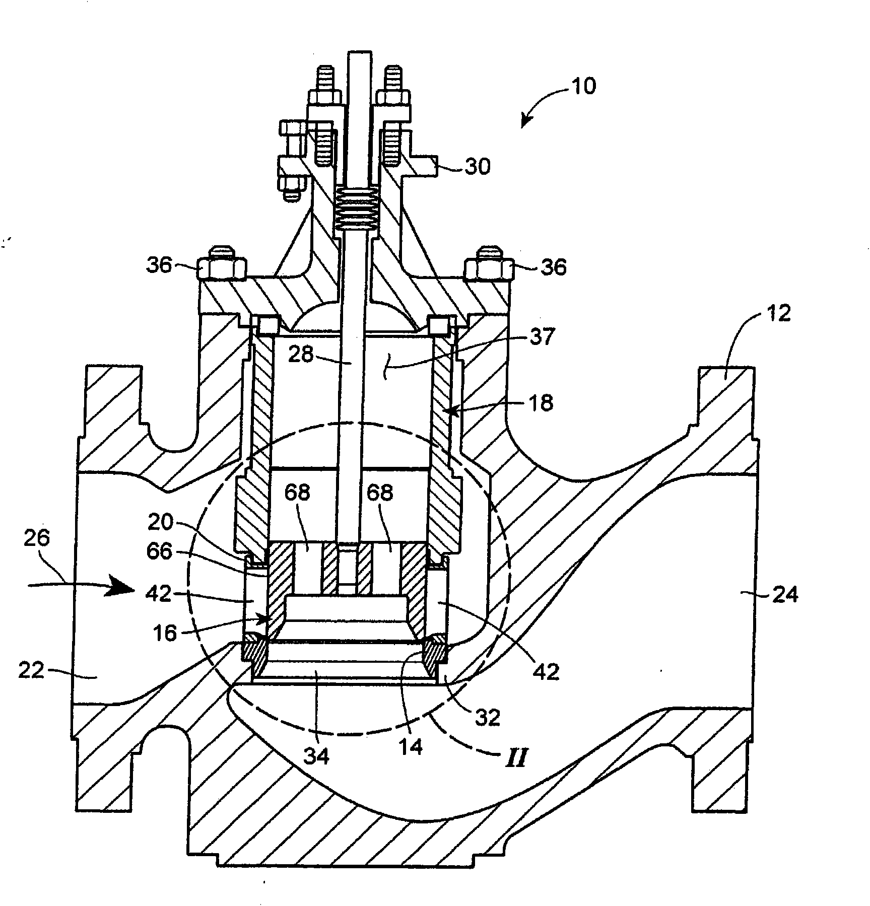
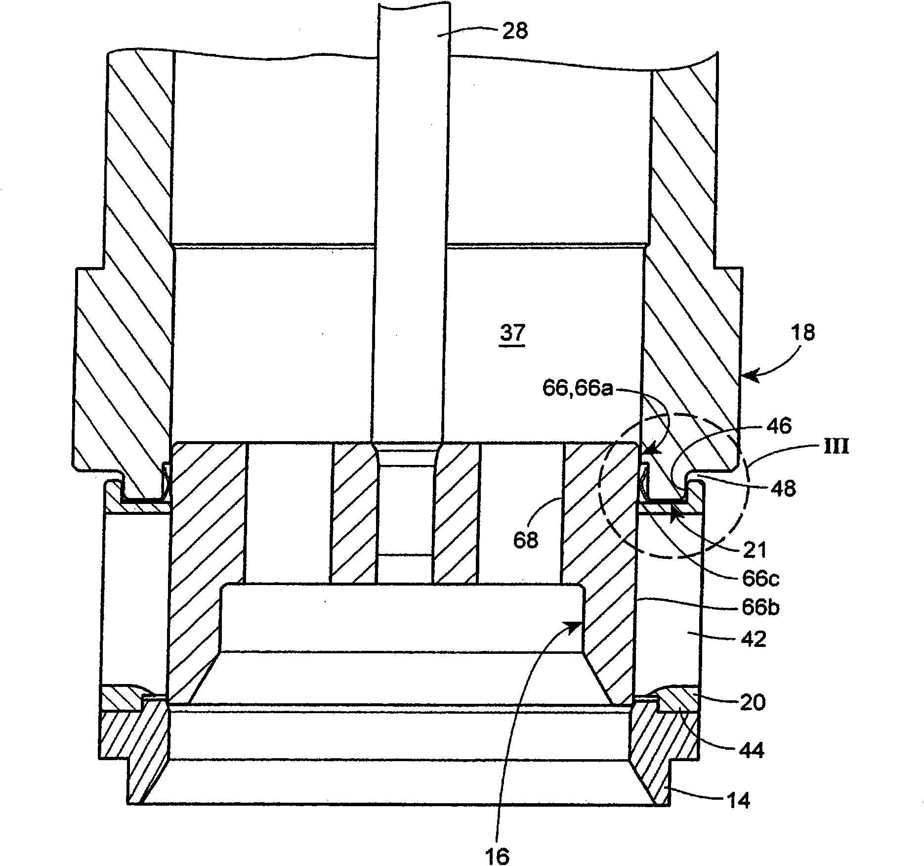
[0008] figure 1 One embodiment of a control valve 10 constructed in accordance with the principles of the present invention is shown. The control valve 10 generally includes a valve body 12, a bonnet 30, a cage retainer 18, a cage 20, a sealing ring 21 (in figure 2 shown in), the valve plug 16 and the valve seat 14. Valve body 12 defines an inlet aperture 22 , an outlet aperture 24 , and a fluid flow path 26 extending between inlet aperture 22 and outlet aperture 24 . The valve plug 16 is coupled to the end of a valve stem 28 which extends through a valve cap 30 and is adapted to be coupled to an actuator (not shown). The actuator controls the spool 16 in the closed position (in figure 1 shown in ) and an open position (not shown) in which the valve plug engages the valve seat 14 to define a primary seal and an open position (not shown) in which the valve plug clears the valve seat 14 . Seal ring 21 provides a secondary seal between cage retainer 18 and cage 20 . In the ...


PUM


Abstract

A fluid control device comprises a valve body (12), a valve plug (16), a valve cage (18,20), and a sealing ring (21). At least a portion of the sealing ring (21) is disposed within a gap (74) between the valve plug (16)and the valve cage (18, 20) to provide a seal therebetween when the valve plug (16) is in the closed position. The sealing ring (21) includes an L-shaped cross-section that provides an effective seal regardless of the port diameter of the fluid control device, and thus, reduces the number of types of seals required to be stored in inventory for various applications.

Description

technical field [0001] The present invention relates to control valves for controlling fluid flow, and more particularly, to control valves including a valve plug movably disposed in a cage. Background technique [0002] Commonly used fluid process control systems include various components used to control various process parameters. For example, a fluid process control system may include a plurality of control valves for controlling the flow, temperature and / or pressure of media flowing through the system. The final product depends on the control accuracy of these parameters, which in turn depends on the geometry and characteristics of the control valve. For example, control valves are specially designed and selected for specific flow and pressure changes. If and when these properties are compromised, the quality of the final product will suffer. One reason the properties may be compromised is inadvertent leaks in the process. Contents of the invention [0003] One em...

Claims


Application Information

Patent Timeline
Patent Type & Authority Applications(China)
IPC IPC(8): F16K47/08
CPCF16K47/08F16K15/142
Inventor L·E·弗莱明
Owner FISHER CONTROLS INT LLC
Why Eureka
Try Eureka