
End mill with varying helix angles

An end mill and helix angle technology, applied in the field of end mills with variable helix angle, can solve the problem that the vibration of the milling cutter cannot be prevented, and achieve the effect of reducing the danger of vibration

Active Publication Date: 2010-12-15
SANDVIK INTELLECTUAL PROPERTY AB
View PDF3 Cites 11 Cited by
  • Summary
  • Abstract
  • Description
  • Claims
  • Application Information

AI Technical Summary

Problems solved by technology

[0007] This can lead to vibrations of the milling cutter not being damped to the extent inherently expected for different cutting edge distances

Method used


Image

  • End mill with varying helix angles
  • End mill with varying helix angles
  • End mill with varying helix angles

Examples


Embodiment Construction

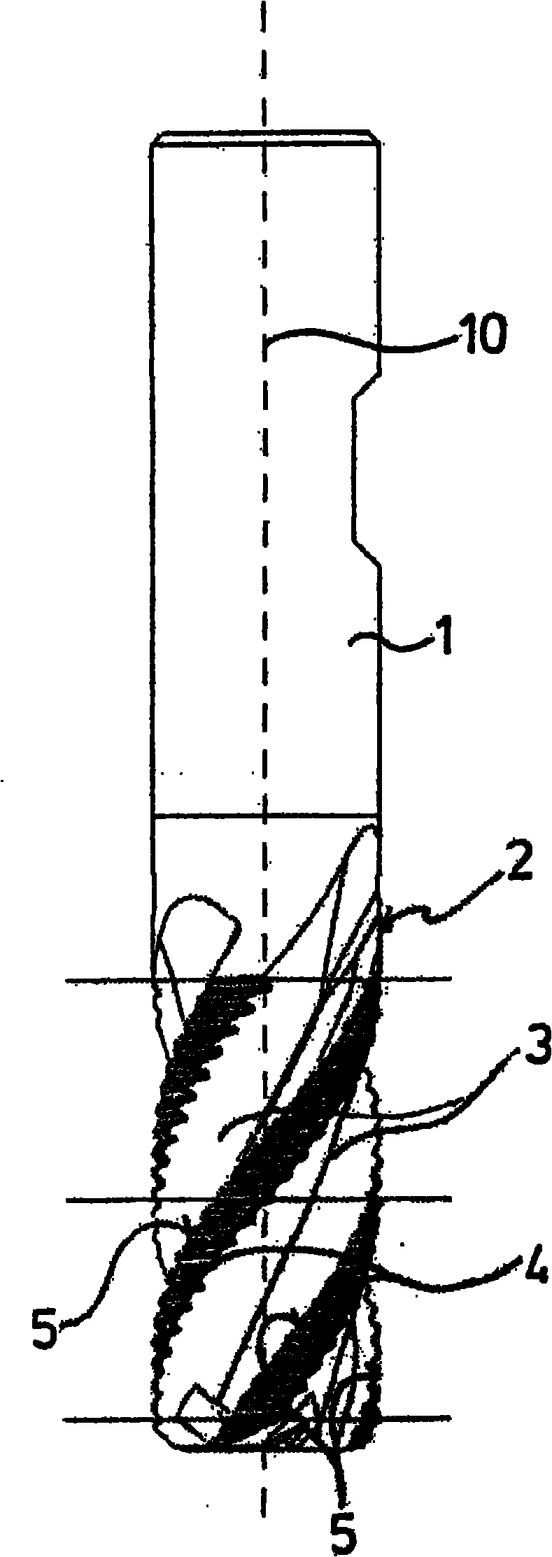
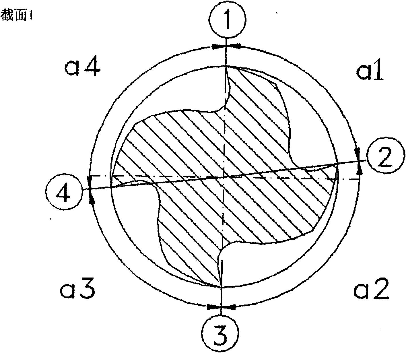
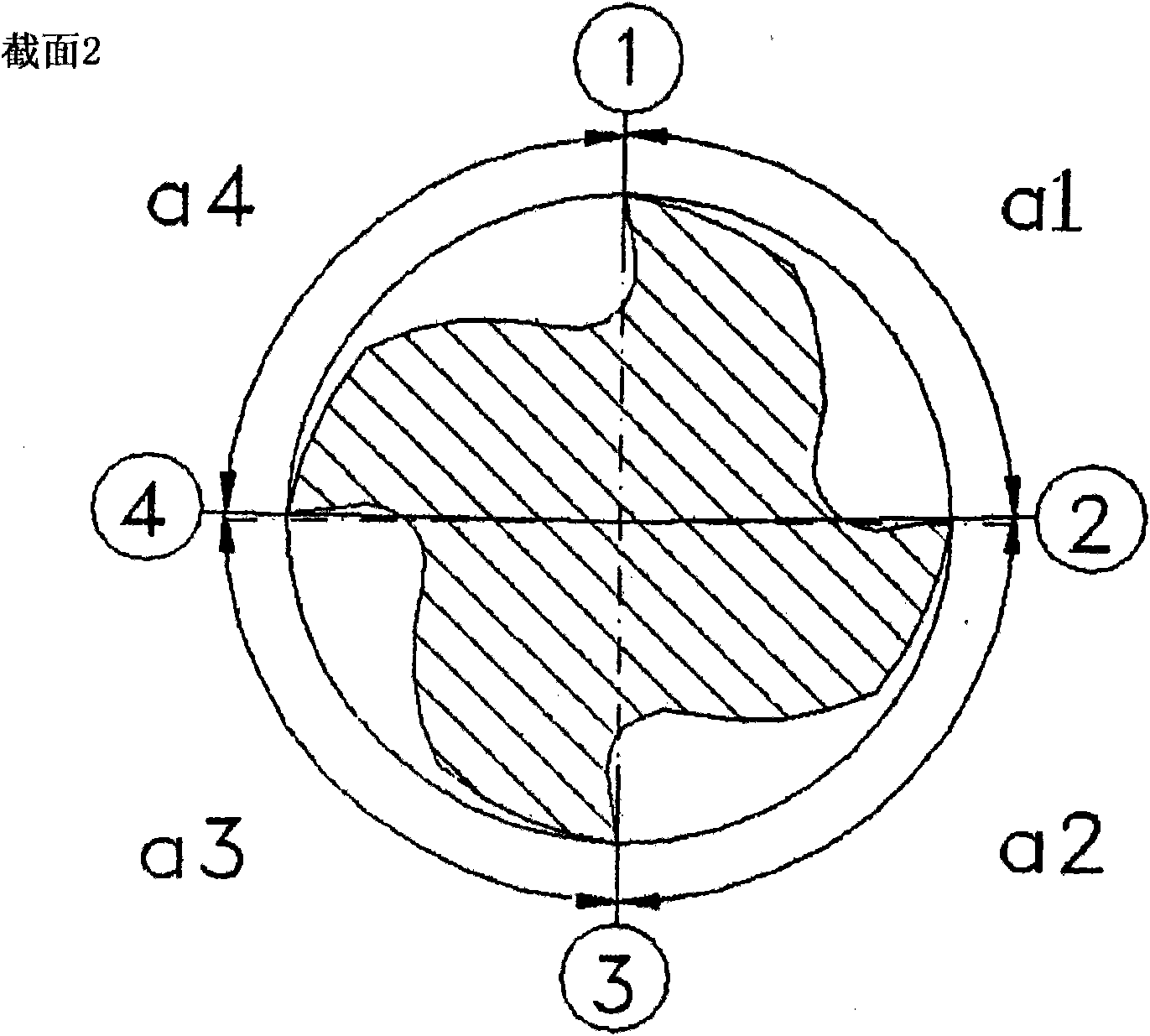
[0032] refer to figure 1 , shows an end mill comprising a mounting end 1 and a cutting portion 2 in plan view. Cutting part 2 includes chip flute 3 and cutting in the middle Figure 4 , each intermediate cutting figure defines a helical circular cutting edge 5 . The cutting edges extending helically around the axis 10 of the milling cutter show respectively different angles of inclination α and β with respect to the axis 10 . in all references to the same embodiment Figures 2 to 5 , different sections through the cutting portion 2 and perpendicular to the axis 10 are shown, while in Figure 5 In , the outer surface of the milling cutter, or rather only its cutting edge 5, is shown unfolded into one plane. figure 2 The locations of the cross-sections shown correspond to figure 1 The section line II-II in the image 3 The section shown in the corresponding figure 1 Section line III-III in, and Figure 4 The section shown in the corresponding figure 1 Section line IV-I...


PUM


Abstract

The present invention relates to an end mill, primarily for coarse machining of metallic work pieces, comprising an even number of main flutes (1-4) that spiral around the periphery of the mill, said flutes having a relatively smaller and a relatively larger helix angle relative to the axis of the mill and wherein uneven-numbered main flutes are defined in that they include the smaller helix angle with the axis. Directly at the end face, the distances between peripheral angles (a1, a2) of the successive main flutes in the direction of rotation are smaller between the uneven-numbered main flutes (1, 3) and the subsequent even-numbered main flutes (2, 4) than the distances between peripheral angles (a2, a4) between the even-numbered main flutes (2, 4) and the subsequent uneven-numbered main flutes (1, 3). In order to provide an end mill with the features mentioned above which is better able to prevent vibrations of the tool due to intermittent engagement with a work piece, according to the invention all distances between peripheral angles at the end face of the mill are different from one another.

Description

technical field [0001] The present invention relates to an end mill for rough machining of metal workpieces, the end mill comprising an even number of main cutting edges extending helically around the circumference of the end mill, said main cutting edges alternating with the axis of the end mill form relatively small helix angles and relatively large helix angles, wherein the odd-numbered cutting edges are defined as those cutting edges that form relatively small helix angles with the axis, and wherein, immediately after the end mill The circumferential angular distance between the odd-numbered main cutting edges and the even-numbered main cutting edges that follow them in the direction of rotation is less than the distance between the even-numbered main cutting edges and the odd-numbered main cutting edges that follow them in the direction of rotation Circumferential angular distance. Background technique [0002] It should be noted that the definitions of "even" and "odd...

Claims


Application Information

Patent Timeline
Patent Type & Authority Applications(China)
IPC IPC(8): B23C5/10
CPCB23C2210/0492B23C2210/282B23C2210/0485B23C5/10Y10T407/1946Y10T407/1962
Inventor 毛里齐奥·塔尔迪沃
Owner SANDVIK INTELLECTUAL PROPERTY AB
Learn More