Floating structure

A technology for structures and floating bodies, which is applied in the directions of floating buildings, ship hulls, hydrodynamic characteristics/hydrostatic characteristics, etc., and can solve the problems of reducing the sway of structures that cannot be floated.

Inactive Publication Date: 2010-12-15
MITSUBISHI HEAVY IND LTD
View PDF5 Cites 19 Cited by
  • Summary
  • Abstract
  • Description
  • Claims
  • Application Information

AI Technical Summary

Problems solved by technology

[0005] However, when the floating structures disclosed in the above-mentioned Patent Documents 1 and 2 are used in marine resource excavation bases, floating recreational facilities or hotels, etc., the swing of the floating structure cannot be reduced to a specified range, and it is necessary to further improvement

Method used


Image

  • Floating structure
  • Floating structure
  • Floating structure

Examples


Embodiment Construction

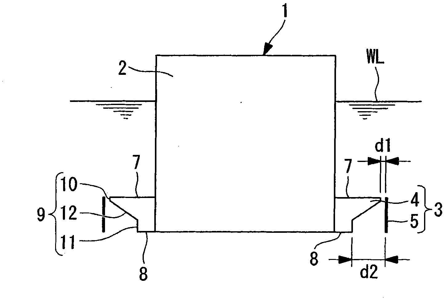
[0075] Below, refer to Figure 1 and figure 2 The first embodiment of the floating body structure of the present invention will be described.

[0076] Figure 1A It is a longitudinal sectional view showing the schematic structure of the floating body structure of this embodiment, Figure 1B is a top view, Figure 1C yes Figure 1B I-I direction view sectional view. in addition, figure 2 It is a graph showing the relationship between the loss coefficient (vertical axis) and the channel cross-sectional area ratio (S0 / S1: horizontal axis).

[0077] also, Figure 1A The symbol WL in is the water surface.

[0078] Such as Figure 1A and Figure 1B As shown, the floating body structure 1 is a structure composed of a column (floating body main body) 2 and a lower shell (protruding structure) 3 as main elements.

[0079] The column 2 is, for example, a cylindrical structure made of a steel plate, and a plurality of airtight floating chambers (not shown) are provided inside.

...


PUM


Abstract

A floating structure whose range of rocking motion is reduced to a level suitable for marine resource drilling platforms, floating leisure facilities, hotels, and so forth (for example, within a range in which work such as writing and walking are possible, that is, generally within a range of 3 DEG - 5 DEG roll motion). The floating structure (1) has a floating body (2) and a plate-like surrounding wall (5) continuously surrounding in the perimetric direction a projection structure part (4) installed on the lower end of the floating body (2). The surrounding wall (5) is installed so that the area of a gap formed between the upper end or the lower end of the surrounding wall (5) and the outer peripheral surface of the projecting structure part (4) is equal to or less than 20% of the area of a gap formed between the lower end of the surrounding wall (5) and the outer peripheral surface of the projection structural part (4).

Description

technical field [0001] The invention relates to a floating body structure, for example, it relates to a marine resource excavation base, a floating body type leisure facility or a floating body structure such as a hotel. Background technique [0002] As such a floating structure, for example, the floating structures disclosed in patent documents 1 and 2 are known. [0003] Patent Document 1: Japanese Patent No. 2772109 [0004] Patent Document 2: International Publication No. WO2005 / 080189A1 [0005] However, when the floating structures disclosed in the above-mentioned Patent Documents 1 and 2 are used in marine resource excavation bases, floating recreational facilities or hotels, etc., the swing of the floating structure cannot be reduced to a specified range, and it is necessary to further improvement. [0006] Here, the external disturbances that stimulate the swing include short-period (several seconds to 30 seconds) swings (six degrees of freedom) excited by fluctu...

Claims


Application Information

Patent Timeline
Patent Type & Authority Applications(China)
IPC IPC(8): B63B35/44B63B39/03B63B39/06
CPCB63B1/107B63B2039/065B63B35/44B63B2039/067B63B39/06B63B2001/044
Inventor 太田真南浦纯一西垣亮谷垣信吉
Owner MITSUBISHI HEAVY IND LTD
Why Eureka
Try Eureka