Counterweight device for elevator

A technology of elevators and counterweights, which is applied to elevators in buildings, transportation and packaging, and lifting equipment in mines, etc. It can solve problems such as adjustability that cannot meet the requirements of high-speed elevators, and heavy irons detachment. The risk of falling off, the effect of enhanced stability and convenient adjustment

Inactive Publication Date: 2010-12-22
CANNY ELEVATOR
View PDF6 Cites 7 Cited by
  • Summary
  • Abstract
  • Description
  • Claims
  • Application Information

AI Technical Summary

Problems solved by technology

The counterweight device of this structure adopts a single-row structure, and its adjustability cannot meet the requirements of high-speed elevators.
Especially in the case of large counterweight guide rail distance, when the elevator is running at high speed, a counterweight iron plate is prone to the phenomenon of counterweight iron detachment

Method used


Image

  • Counterweight device for elevator
  • Counterweight device for elevator
  • Counterweight device for elevator

Examples


Embodiment Construction

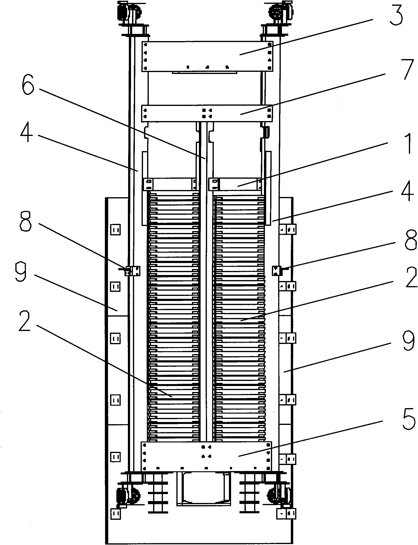
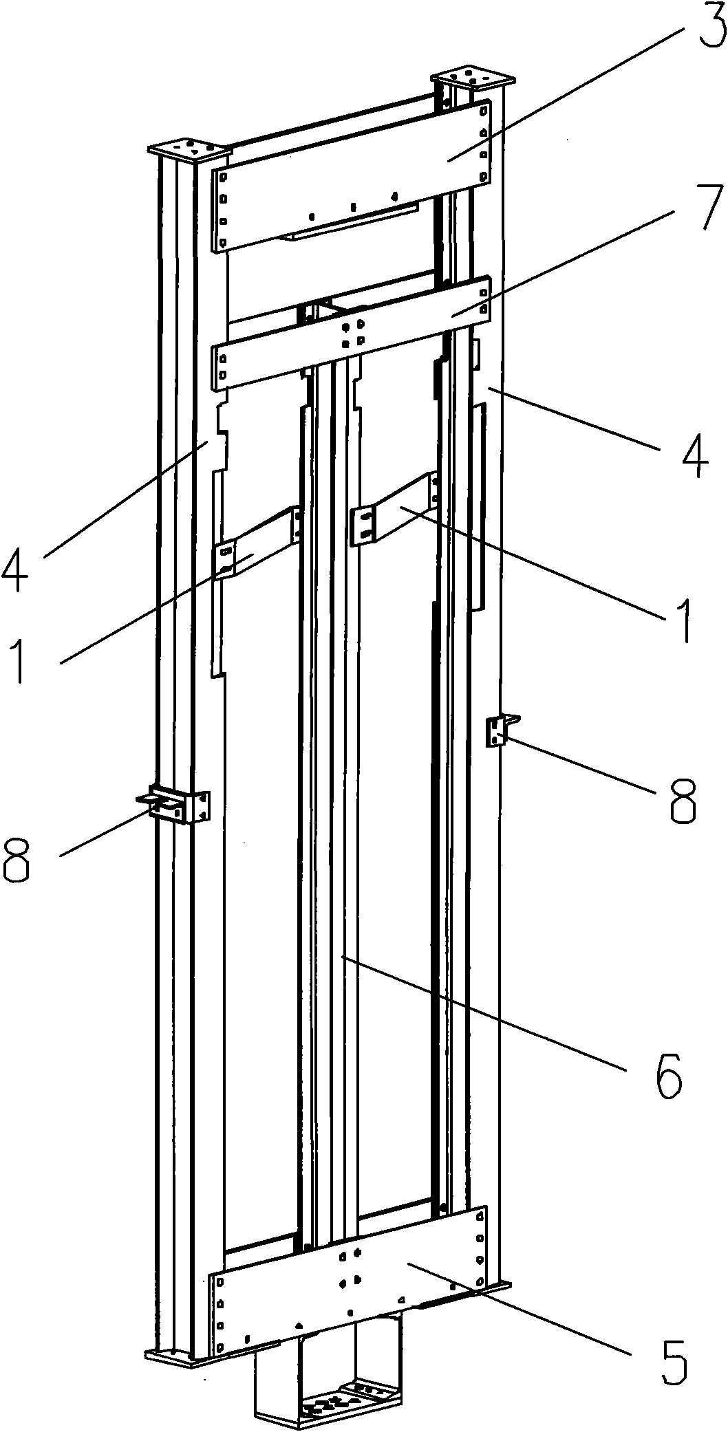
[0017] Such as figure 1 and figure 2 As shown, a counterweight device for an elevator of the present invention includes a counterweight frame, a counterweight iron pressing plate 1 , a counterweight iron 2 , a short vertical beam 6 and a transverse tie plate 7 . The counterweight frame includes two upper side beams 3, two vertical beams 4 and two lower side beams 5. Two vertical beams 4 are parallel to each other and placed vertically. The two upper side beams 3 are fixedly connected to the tops of the two vertical beams 4, and the two upper side beams 3 are parallel to each other. The two lower side beams 5 are fixedly connected to the lower ends of the two vertical beams 4, and the two lower side beams 5 are parallel to each other. The horizontal tension plate 7 is fixedly connected between the two vertical beams 4 . The short vertical beams 6 are located between the two vertical beams 4 and are parallel to the vertical beams 4 . The bottom ends of the short upright be...


PUM


Abstract

The invention relates to a counterweight device for an elevator, comprising counterweight racks, two counterweight iron press plates, counterweight irons, a short vertical beam and a horizontal pull plate, wherein the horizontal pull plate is fixedly connected between two vertical beams; the short vertical beam is positioned between the two vertical beams and is parallel to the vertical beams; the bottom end of the short vertical is fixedly connected to two lower boundary beams; the top end of the short vertical beam is fixedly connected with the horizontal pull plate; the counterweight irons are embedded between the vertical beams and the short vertical beam; and the two counterweight iron press plates are respectively movably connected between the vertical beams and the short vertical beam and are positioned at the upper ends of the counterweight irons. In the technical scheme, the whole counterweight device is arranged in the left counterweight rack and the right counterweight rack. The counterweight irons are respectively embedded in the left counterweight rack and the counterweight rack. The two counterweight press plates respectively press the counterweight irons in the counterweight racks so as to enhance the stability. Meanwhile, by adopting a dual-row structure, the invention can provide enough strength and space for placing a proper amount of counterweight irons and is convenient to adjust.

Description

technical field [0001] The invention relates to a balancing device for an elevator, in particular to a counterweight device for an elevator. Background technique [0002] In the elevator, the counterweight device is an indispensable part of the traction elevator, it can balance the weight of the car and part of the elevator load weight, and reduce the loss of motor power. The counterweight device of an ordinary elevator includes two upper side beams, two vertical beams, two lower side beams, a counterweight iron platen and a counterweight iron. The two vertical beams are parallel to each other. The two upper beams are parallel and fixedly connected to the tops of the two vertical beams. The two bottom beams are parallel and fixedly connected to the lower ends of the two vertical beams. The counterweight iron is embedded between the two vertical beams. The counterweight iron pressing plate is movably connected between the two vertical beams, and the counterweight iron pre...

Claims


Application Information

Patent Timeline
Patent Type & Authority Applications(China)
IPC IPC(8): B66B11/00B66B17/12
CPCB66B17/12
Inventor 张建宏俞诚王亮亮
Owner CANNY ELEVATOR
Why Eureka
Try Eureka