Supercharge Your Innovation With Domain-Expert AI Agents!

Paper cutting machine

A paper machine and frame technology, applied in the field of processing machinery, can solve the problems of low work efficiency, inevitable defective products, high labor costs, etc., and achieve the effects of improving work efficiency, reducing manpower into machines, and improving safety

Active Publication Date: 2010-12-22
ZHUHAI HUAFENG PAPER
View PDF5 Cites 0 Cited by
  • Summary
  • Abstract
  • Description
  • Claims
  • Application Information

AI Technical Summary

Problems solved by technology

[0002] In the production of the paper industry, the produced paper needs to be rolled into large rolls by winding equipment, but defective products are unavoidable in the production process, which requires cutting the wound paper rolls and recycling them again. The existing method The paper is split manually, but because the paper roll is often very thick, it is necessary to repeatedly scratch the surface of the paper roll with a knife during work to peel off the layers of the paper roll
This traditional recycling method not only has extremely low work efficiency and high labor costs, but also workers' hands are easily cut by sharp paper edges during operation

Method used


Image

  • Paper cutting machine
  • Paper cutting machine
  • Paper cutting machine

Examples


Embodiment Construction

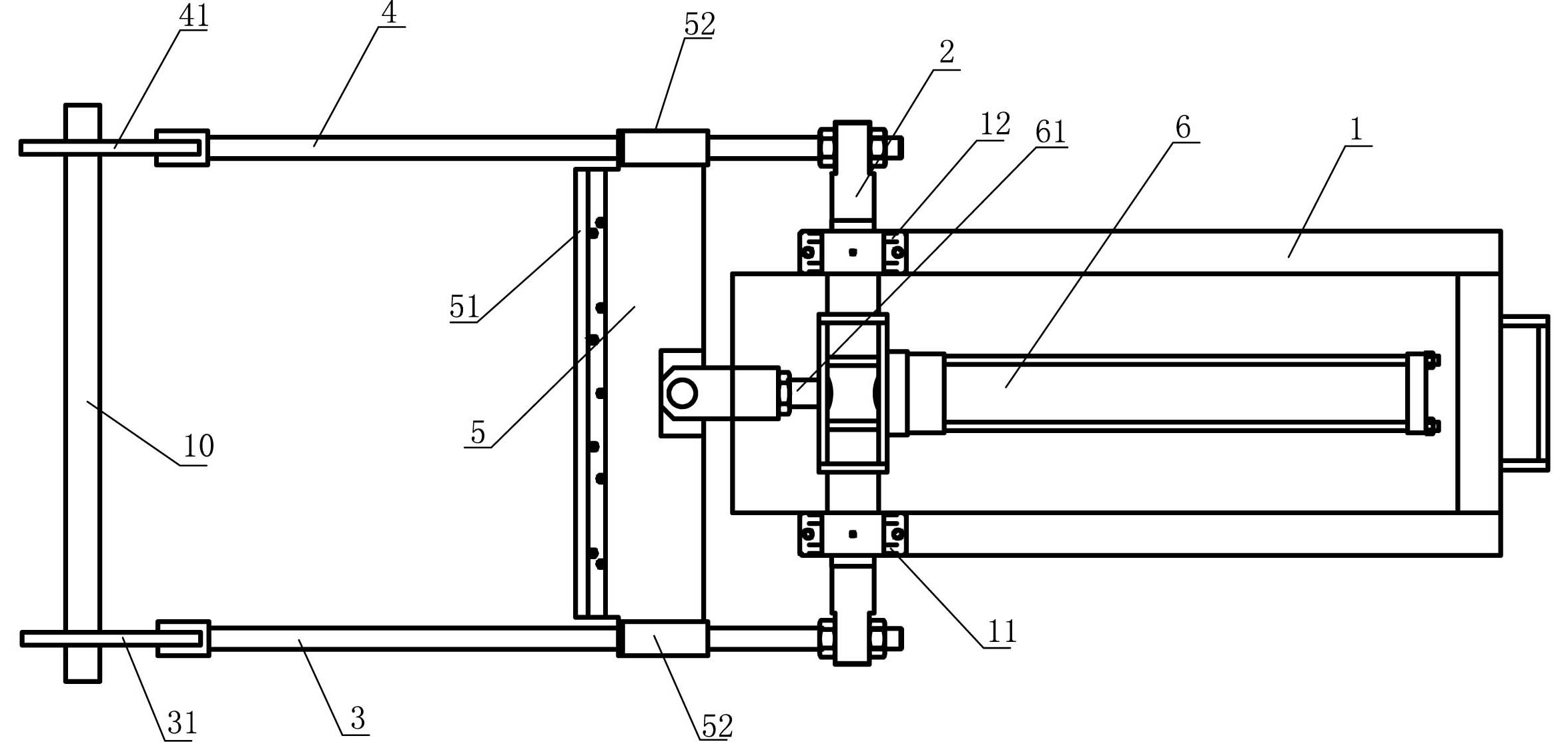
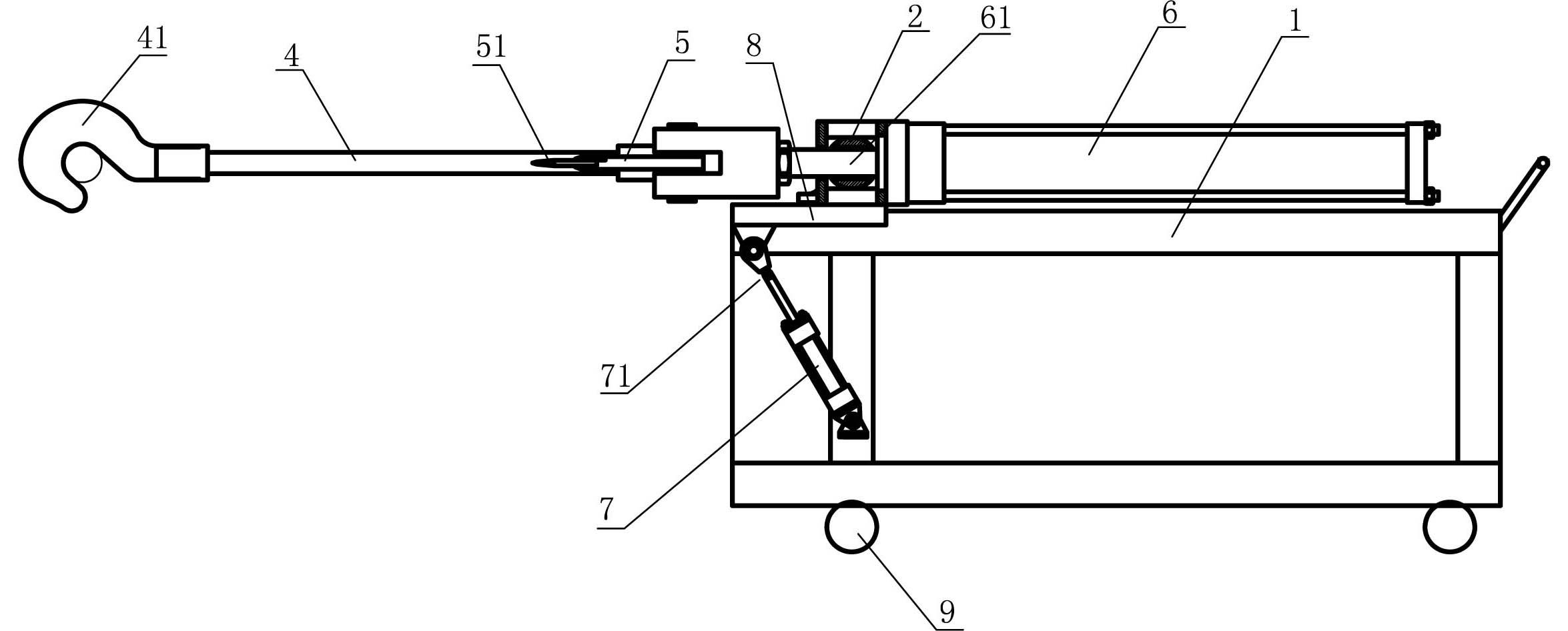
[0012] refer to figure 1 , figure 2 As shown, a paper splitter includes a frame 1, a main shaft 2, left and right tie rods 3, 4, a knife seat 5 and a cutter 51, and the main shaft 2 is laterally installed on the frame 1 through left and right bearing seats 11, 12. Up, the left and right pull rods 3,4 are fixed on the two ends of the main shaft 2, the left and right pull rods 3,4 protrude forward, and the front ends of the left and right pull rods 3,4 are provided with drag hooks or pull rings 31,41; the main shaft 2 A hydraulic cylinder 6 is fixed, and the telescopic arm 61 of the hydraulic cylinder 6 is connected to the knife seat 5. The knife seat 5 is equipped with a cutter 51. The two ends of the knife seat 5 are respectively provided with sliding sleeves 52, and the sliding sleeves 52 are respectively sleeved on the left and right pull rods. On 3,4; Frame 1 also installs the second hydraulic cylinder 7 that can make main shaft 2 take left and right bearing seat 11,12 as...


PUM


Abstract

The invention relates to a paper cutting machine which comprises a machine frame, a main shaft, a left draw rod, a right draw rod, a knife file and a cutting knife, wherein the main shaft is transversely installed on the machine frame through a left bearing seat and a right bearing seat; the left and right draw rods are fixed to both ends of the main shaft and protrude forwards; the front ends of the left and right draw rods are respectively provided with a draw hook or a draw ring; a hydraulic cylinder is fixed to the main shaft; a telescopic arm of the hydraulic cylinder is connected with the knife file; the knife file is provided with the cutting knife; both ends of the knife file are respectively provided with a slide sleeve; and the slide sleeves are respectively sheathed on the left and right draw rods; and the machine frame is also provided with a second hydraulic cylinder which can enable the main shaft to rotate around the axial lead of the main shaft by using the left and right bearing seats as a pivot. By replacing the traditional manual operation mode with mechanical devices, the invention enhances the work efficiency, lowers the cost of manpower and enhances the safety.

Description

technical field [0001] The invention relates to a processing machine used in the paper industry, in particular to a paper splitter. Background technique [0002] In the production of the paper industry, the produced paper needs to be rolled into large rolls by winding equipment, but defective products are unavoidable in the production process, which requires cutting the wound paper rolls and recycling them again. The existing method The paper is split manually, but since the paper roll is often very thick, it is necessary to use a knife to repeatedly scratch the surface of the paper roll to peel off the layers of the paper roll. This traditional recycling method not only has extremely low work efficiency and high labor costs, but also workers' hands are easily cut by sharp paper edges during the operation. Contents of the invention [0003] In order to overcome the deficiencies of the prior art, the invention provides a safe and efficient paper splitter. [0004] The te...

Claims


Application Information

Patent Timeline
Patent Type & Authority Applications(China)
IPC IPC(8): D21G9/00
Inventor 冯式忠
Owner ZHUHAI HUAFENG PAPER
Features
  • R&D
  • Intellectual Property
  • Life Sciences
  • Materials
  • Tech Scout
  • Unparalleled Data Quality
  • Higher Quality Content
  • 60% Fewer Hallucinations
Learn More