Photovoltaic roof tile

A photovoltaic and roof tile technology, applied in the field of roof tiles, can solve the problems of low photoelectric conversion rate of photovoltaic tiles, short life of photovoltaic cells, and inability to block wind and rain, and achieve stable power supply, high photoelectric conversion efficiency, and high power utilization rate Effect

Inactive Publication Date: 2010-12-22
浙江贝盛绿能科技有限公司
View PDF9 Cites 15 Cited by
  • Summary
  • Abstract
  • Description
  • Claims
  • Application Information

AI Technical Summary

Problems solved by technology

The roof of a building is the most suitable place to install photovoltaic cells. As a building roof, photovoltaic cells must first meet all the requirements of conventional roofing materials, such as strong aging resistance and impermeability to weather, etc. The means of using electrical appliances to enter the building; traditional photovoltaic cells have a short lifespan and are poorly waterproof, unable to block wind and rain. Therefore, the traditional photovoltaic cell installation method is to install brackets on the original roof of the building, and then erect photovoltaic cells on the brackets Batteries, higher installation cost, more steps, more difficult
[0003] Patent No. CN200710196157.6 discloses a photovoltaic tile that can be used directly as a roofing material, but the photoelectric conversion rate of this photovoltaic tile is low and the structure is complex

Method used


Image

  • Photovoltaic roof tile
  • Photovoltaic roof tile
  • Photovoltaic roof tile

Examples


Embodiment 1

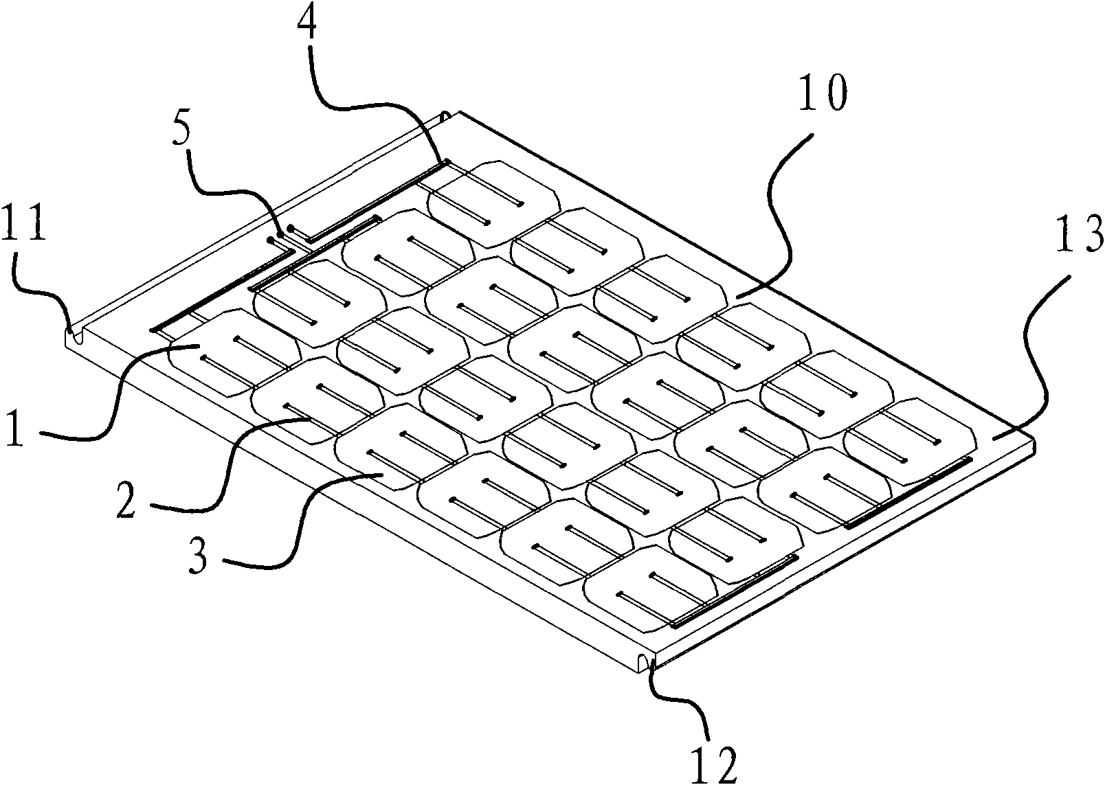
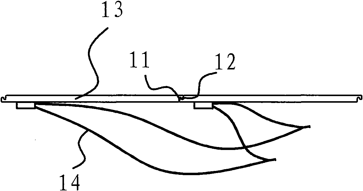
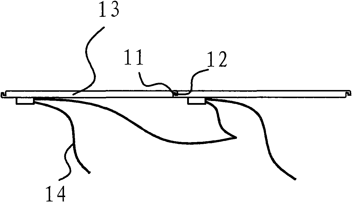
[0031] A photovoltaic roof tile, such as figure 1 , 2 As shown, including photovoltaic wafer 1, photovoltaic wafer 1 includes 24 silicon cells 3, interconnection bar 2 is welded between the positive pole of silicon cells 3 and the negative pole of adjacent silicon cells 3, the positive electrode of first silicon cells 3 A bus bar 4 is welded to the negative electrode of the tail block silicon cell 3; the photovoltaic chip 1 is provided with encapsulation material, the encapsulation material includes flat glass and a tile-type back material 13, and the flat glass is attached to the front of the photovoltaic chip 1 in a tile-type The front of the back material 13 is rectangular and is provided with a cavity, which is made of ceramics. The photovoltaic chip 1 and flat glass are packaged in the cavity of the tile-type back material 13, and one side edge of the tile-type back material 13 is provided with a The positive edge 11 that the front of tile-type back material protrudes, a...

Embodiment 2

[0036] The difference from the first embodiment is that the apexes of the protruding cross-sections of the front rib 11 and the back rib 12 are both square.

[0037] During installation, the positive pole of the power line 14 is connected to the negative pole of the adjacent photovoltaic roof tile power line 14 through the socket.

Embodiment 3

[0039] The difference from the first embodiment lies in that a locking edge 15 is provided on the protruding top ends of the front edge 11 and the back edge 12 .

[0040] During installation, the back edge 12 of the photovoltaic roof tile overlaps with the front edge 11 of the adjacent photovoltaic roof tile, and the locking edge 15 on the back edge 12 and the locking edge 15 on the front edge 11 of the adjacent photovoltaic roof tile are interlocked and locked .


PUM


Abstract

The invention discloses a photovoltaic roof tile comprising a photovoltaic chip, and a packaging material is arranged outside the photovoltaic chip. The invention is characterized in that the packaging material comprises surface material and tile-type back material, wherein the surface material is stuck on the right side of the photovoltaic chip, the tile-type back material is stuck on the reverse side of the photovoltaic chip, and the edge of the tile-type back material is provided with a lap joint structure. The installation mode of the invention is completely same with that of the traditional tile. The photovoltaic roof tile does not need a bracket, is convenient to install, has the advantages of the traditional tile, is weathertight, has long service life, and has high photoelectric conversion efficiency and electric energy output power.

Description

technical field [0001] The invention relates to a roof tile, in particular to a roof tile integrating photovoltaic cells or solar cells. Background technique [0002] As a renewable energy source, solar energy has the advantages of cleanliness and environmental protection. In today's deteriorating environment, solar energy is being used more and more. Photoelectric technology, as a better way to utilize solar energy, is gradually becoming an important means of power generation. The roof of a building is the most suitable place to install photovoltaic cells. As a building roof, photovoltaic cells must first meet all the requirements of conventional roofing materials, such as strong aging resistance and impermeability to weather, etc. The means of using electrical appliances to enter the building; traditional photovoltaic cells have a short lifespan and are poorly waterproof, unable to block wind and rain. Therefore, the traditional photovoltaic cell installation method is to ...

Claims


Application Information

Patent Timeline
Patent Type & Authority Applications(China)
IPC IPC(8): E04D13/18H01L31/048H02N6/00H02S20/25
CPCY02E10/50Y02B10/12Y02B10/10
Inventor 王琰琨嗡晔
Owner 浙江贝盛绿能科技有限公司
Why Eureka
Try Eureka