Self-limiting electronic gear shifter

An electronic shifter, self-limiting technology, applied in the direction of components with teeth, belts/chains/gears, mechanical equipment, etc. Increase the front space and operating comfort, ensure safety, good sealing effect

Active Publication Date: 2010-12-22
HANGCHA GRP
10 Cites 23 Cited by

AI-Extracted Technical Summary

Problems solved by technology

[0002] An electronic shifter is an indispensable actuator for driving a vehicle. The existing electronic shifter mainly includes a base, a cover body, a shift lever, a cam seat and a shift switch. The cover body is arranged on the base A chamber is formed, the cam seat and the shift switch are arranged in the chamber, the shift switch is in contact with the cam seat, the shift lever is connected with the cam seat, and the cover body is provided with a The matching chute drives the cam seat to move a group of switches to control the solenoid valve through the forward and backward movement of the shi...

Method used

As shown in Figures 1 and 2, the self-limiting electronic shifter described in this embodiment mainly includes a base 1, a cover body 10, a shift lever 7, a cam seat 3 and a shift switch 2, The cover body 10 is arranged on the base 1 to form a chamber, the cam seat 3 and the shift switch 2 are arranged in the chamber, the shift switch 2 is in contact with the cam seat 3, the shift lever 7 is connected with the cam seat 3, and the cover The body 10 is provided with a chute matched with the shift lever 7. The shift lever 7 is mainly composed of an outer rod 8 which can be pressed down and a connecting rod 6 arranged inside the outer rod 8. The top of the connecting rod 6 is connected with the outer rod. 8 is provided with spring 149, and its other end is connected with cam seat 3; Also be provided with arc groove 13 in the chamber, be provided with two limit seats 4 in the chamber, cam seat 3 is connected in the middle of them by rotating shaft 17, arc The groove 13 is arranged on the two limit seats 4; a limit body is also connected to the outer rod 8, and the limit body is arranged in the arc groove 13 at the same time, and the position corresponding to each gear position on the arc groove 13 is There is a limiting groove matched with the limiting body. The limit groove is an arc groove 13, and the limit body is a roller 12. The casing is provided with an arc paddle 5 for sealing the chute, which can realize good sealing of the chute on the casing when shifting gears. In order to prevent relative rotation between the outer rod 8 and the connecting rod 6, a longitudinally movable positioning structure composed of a positioning pin 11 and a positioning groove is provided between the outer rod 8 and the connecting rod 6, which can achi...

Abstract

The invention discloses a self-limiting electronic gear shifter. The gear shifter mainly comprises a pedestal, a housing, a gear shift lever, a cam seat and a gear shift switch, wherein the housing is arranged on the pedestal to form a chamber; the cam seat and the gear shift switch are arranged in the chamber; the gear shift switch is contacted and matched with the cam seat; the gear shift leveris connected with the cam seat; the housing is provided with a sliding chute which is matched with the gear shift lever; the gear shifter is characterized in that the gear shift lever mainly comprises an outer rod capable of being pressed down and a connecting rod arranged in the outer rod; a spring is arranged between the top of the connecting rod and the outer rod, and the other end of the connecting rod is connected with the cam seat; a circular arc groove is also formed in the chamber; the outer rod is also connected with a limiting body which is also arranged in the circular arc groove; and the circular arc groove is provided with a limiting groove which is matched with the limiting body along a corresponding part of each gear position. The self-limiting electronic gear shifter of the invention has a self-locking function, so that the operating safety of vehicles is ensured, and good handfeel is achieved during gear shifting.

Application Domain

Technology Topic

Self limitingSelf locking +2

Image

  • Self-limiting electronic gear shifter
  • Self-limiting electronic gear shifter
  • Self-limiting electronic gear shifter

Examples

  • Experimental program(2)

Example Embodiment

[0019] Example 1
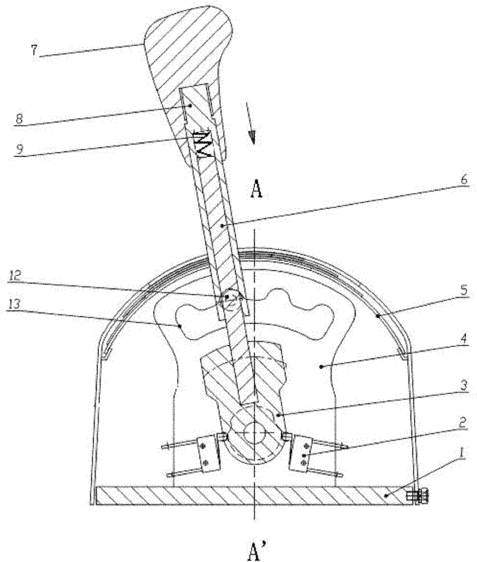
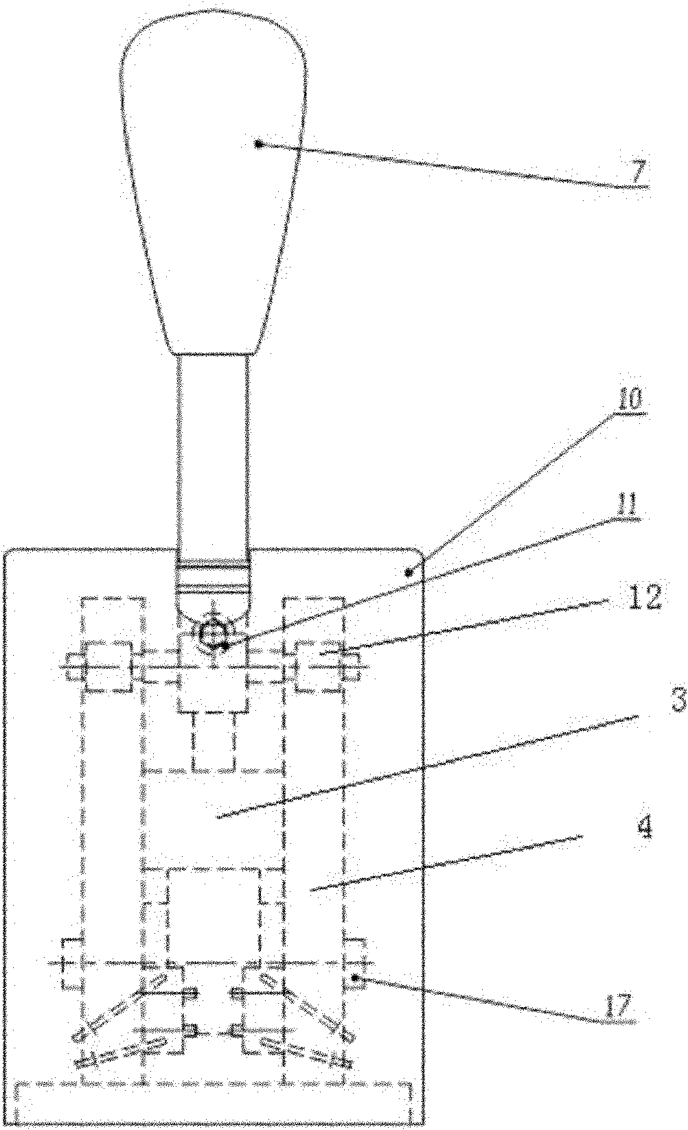
[0020] like figure 1 , 2 As shown, the self-limiting electronic shifter described in this embodiment mainly includes a base 1, a cover body 10, a shift lever 7, a cam seat 3 and a shift switch 2, and the cover body 10 is arranged on the base 1 A chamber is formed, the cam seat 3 and the shift switch 2 are arranged in the chamber, the shift switch 2 is in contact with the cam seat 3, the shift lever 7 is connected with the cam seat 3, and the cover body 10 is provided with a The chute that the rod 7 matches, the shift rod 7 is mainly composed of a depressible outer rod 8 and a connecting rod 6 arranged inside the outer rod 8, a spring 149 is arranged between the top of the connecting rod 6 and the outer rod 8, The other end is connected to the cam seat 3; an arc groove 13 is also provided in the chamber, and two limit seats 4 are arranged in the chamber, the cam seat 3 is connected between them by a rotating shaft 17, and the arc groove 13 is arranged on two limit seats. On the seat 4; the outer rod 8 is also connected with a limit body, the limit body is set in the arc groove 13 at the same time, and the arc groove 13 is provided with the corresponding position along each gear position to cooperate with the limit body. limit slot. The limit groove is an arc groove 13, and the limit body is a roller 12. The casing is provided with an arc paddle 5 for sealing the chute, which can realize good sealing of the chute on the casing when shifting gears. In order to prevent relative rotation between the outer rod 8 and the connecting rod 6, a longitudinally movable positioning structure composed of a positioning pin 11 and a positioning groove is provided between the outer rod 8 and the connecting rod 6, which can achieve a good positioning effect. It does not affect the depressing operation of the outer rod 8 again.
[0021] When in use, the wire plug drawn from the shift switch 2 is connected with the plug drawn from the gearbox to realize the gear shifting function of the gearbox. When there is no need to shift gears, the outer rod 8 is lifted due to the action of the spring 149, and the roller 12 on the outer rod 8 is located in one of the arc grooves 13 of the limit seat 4. When the shifter shifts gears, press the outer rod 8. The roller 12 on the outer rod 8 will withdraw from the arc groove 13 of the limit seat 4 to release the self-locking, push the handle to the corresponding gear position, the shift lever 7 drives the cam seat 3 to rotate together through the connecting rod 6, and drives the corresponding The gear switch works to realize gear shifting. At this time, after the shift lever 7 is released, the outer rod 8 drives the roller 12 to move up through the return spring 149, and the roller 12 is inserted into the arc groove 13 of the limit seat 4 to realize self-locking. The shift lever 7 will not shift under the direct toggle of external force, thus ensuring the safety of vehicle operation, thus the shifter can be installed on the right side of the driver, increasing the front space of the driver and operating comfort sex.
[0022] Certainly, those of ordinary skill in the art should be able to make similar changes according to the above-mentioned prompts in combination with the prior art, such as the arc groove 13 in the chamber is not limited to the scheme that is arranged on the position-limiting seat 4, and can be modified by modifying the cover body 10 For the transformation of the inner wall, the arc groove 13 is arranged on the inner wall of the cover body 10; the structure of the limit groove and the limit body is not limited to the arc groove 13 and the roller 12, and it can also be a square groove and a matching limit. body, a longitudinally movable positioning structure may not be provided between the outer rod 8 and the connecting rod 6 .

Example Embodiment

[0023] Example 2
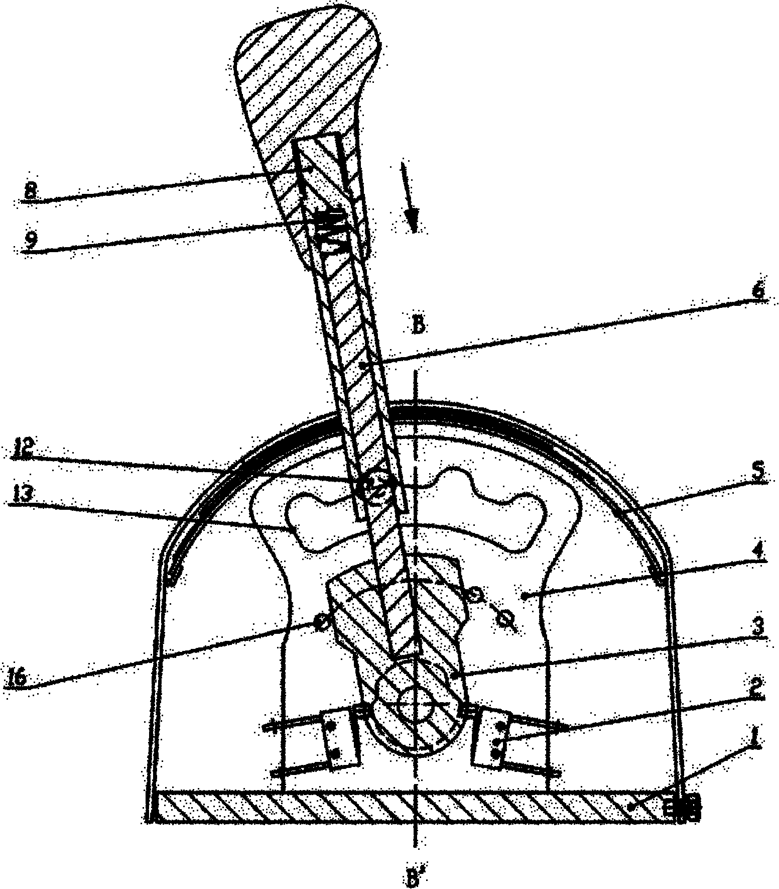
[0024] like image 3 , 4 As shown, in the self-limiting electronic shifter described in this embodiment, on the basis of Embodiment 1, a blind hole is provided on the cam seat 3, and a spring 149 and a ball are arranged in the blind hole, and the ball is a steel ball 15. The corresponding positions of each gear position on the limit seat 4 are provided with pits 16 that cooperate with the balls, so that the driver can obtain a good feel when shifting gears.
[0025] When in use, the wire plug drawn from the shift switch 2 is connected with the plug drawn from the gearbox to realize the gear shifting function of the gearbox. When there is no need to shift gears, the roller 12 on the shift lever 7 is located in one of the arc grooves 13 of the limit seat 4 , and the steel ball 15 is located in one of the pits 16 . When the shifter shifts gears, press the outer lever 8, the roller 12 on the outer lever 8 will withdraw from the arc groove 13 of the limit seat 4 to release the self-locking, push the handle to the corresponding gear, and the shift lever 7 will pass through the connection. The rod 6 drives the cam seat 3 to rotate together (the steel ball 15 comes out of the pit 16 with the rotation of the cam seat 3), and drives the corresponding gear switch to work to realize gear shifting. At this time, the outer rod 8 is driven by the return spring 149 after the handle is released. The roller 12 moves up, and the roller 12 snaps into the arc groove 13 of the limit seat 4 to realize self-locking; at the same time, the steel ball 15 also slides into another pit 16, both of which can realize the driver's good control over a gear shift. feel. And a group of circular arc paddles 5 of different lengths on the casing will also move back and forth on their own tracks along with the rotation of the shift lever 7, pinning down and superimposing, so as to realize the good sealing of the chute on the casing.

PUM

no PUM

Description & Claims & Application Information

We can also present the details of the Description, Claims and Application information to help users get a comprehensive understanding of the technical details of the patent, such as background art, summary of invention, brief description of drawings, description of embodiments, and other original content. On the other hand, users can also determine the specific scope of protection of the technology through the list of claims; as well as understand the changes in the life cycle of the technology with the presentation of the patent timeline. Login to view more.

Similar technology patents

Safety protection method of network feedback host computer

InactiveCN101567888AEnsure safetyUnable to connectData switching networksNetwork behaviorSoftware
Owner:郭世泽 +1

Application information push method, system and network element

ActiveCN102388632ATwo-way information exchangeEnsure safetyInformation formatContent conversionApplication serverService provider
Owner:HUAWEI TECH CO LTD

Classification and recommendation of technical efficacy words

Why Eureka
Try Eureka