Unlock instant, AI-driven research and patent intelligence for your innovation.
Light irradiation device
What is Al technical title?
Al technical title is built by PatSnap Al team. It summarizes the technical point description of the patent document.
A light irradiation device and light source technology, applied in lighting devices, components of lighting devices, optics, etc., can solve problems such as loss of uniformity of illumination
Inactive Publication Date: 2010-12-22
USHIO DENKI KK
View PDF2 Cites 8 Cited by
Summary
Abstract
Description
Claims
Application Information
AI Technical Summary
This helps you quickly interpret patents by identifying the three key elements:
Problems solved by technology
Method used
Benefits of technology
Problems solved by technology
[0022] Thus, even with Figure 17 The segmented light source ensures the uniformity of illuminance. If a light irradiation device is formed, there is also the problem that the uniformity of illuminance is lost between the segmented light sources.
Method used
Image
Click on the blue label to locate the original text in one second.
Reading with bidirectional positioning of images and text.
Examples
example 1
[0125] (Example 1) The case where the size category of the unit cell lens is 3
[0126] Figure 11 (a) is a view of an integrator lens composed of three types of large, medium, and small cell-like lenses viewed from the light incident side, showing superimposition of light from five LEDs A to E (circles in the figure). In addition, here, the size of each unit cell lens is shown by the difference of hatching.
[0127] "Group 1" for this instance, is as in Figure 11 As shown in (b), one set is arranged in the order of middle, small and large from the left, and the so-called "regularly arrange one group" is as follows Figure 11 Shown in (c) refers to the situation where "one set" is arranged obliquely or horizontally in sequence. Thereby, the light from each LED can be incident on the unit cell lens of each size in the same way, and the light from a certain LED can be incident only on, for example, a large-sized unit cell lens, etc. The case where the type of unit cell lens...
example 2
[0130] (Example 2) Situation where the size types of the unit cell lens are 4
[0131] Figure 12 (a) is a view of an integrator lens composed of four types of unit cell lenses: large, medium-large, medium-small, and small, viewed from the light incident side, showing that light from five LEDA-E is superimposed (the circle in the figure).
[0132] "Group 1" for this example, is by Figure 12 (b) A group configured in the order of large, medium-large, medium-small, and small, and the so-called "regularly arrange a group" is as follows Figure 12 Shown in (c) refers to the case where "one set" is arranged vertically or horizontally sequentially.
[0133] In this way, even if the types of cell lenses are increased, as in Example 1, although LEDs that do not light up are produced, by supplementing the light quantity of the LEDs that are not lit with the light quantity of other LEDs, the light is maintained in the same way before and after the LEDs are turned off. Surface illumi...
PUM
Abstract
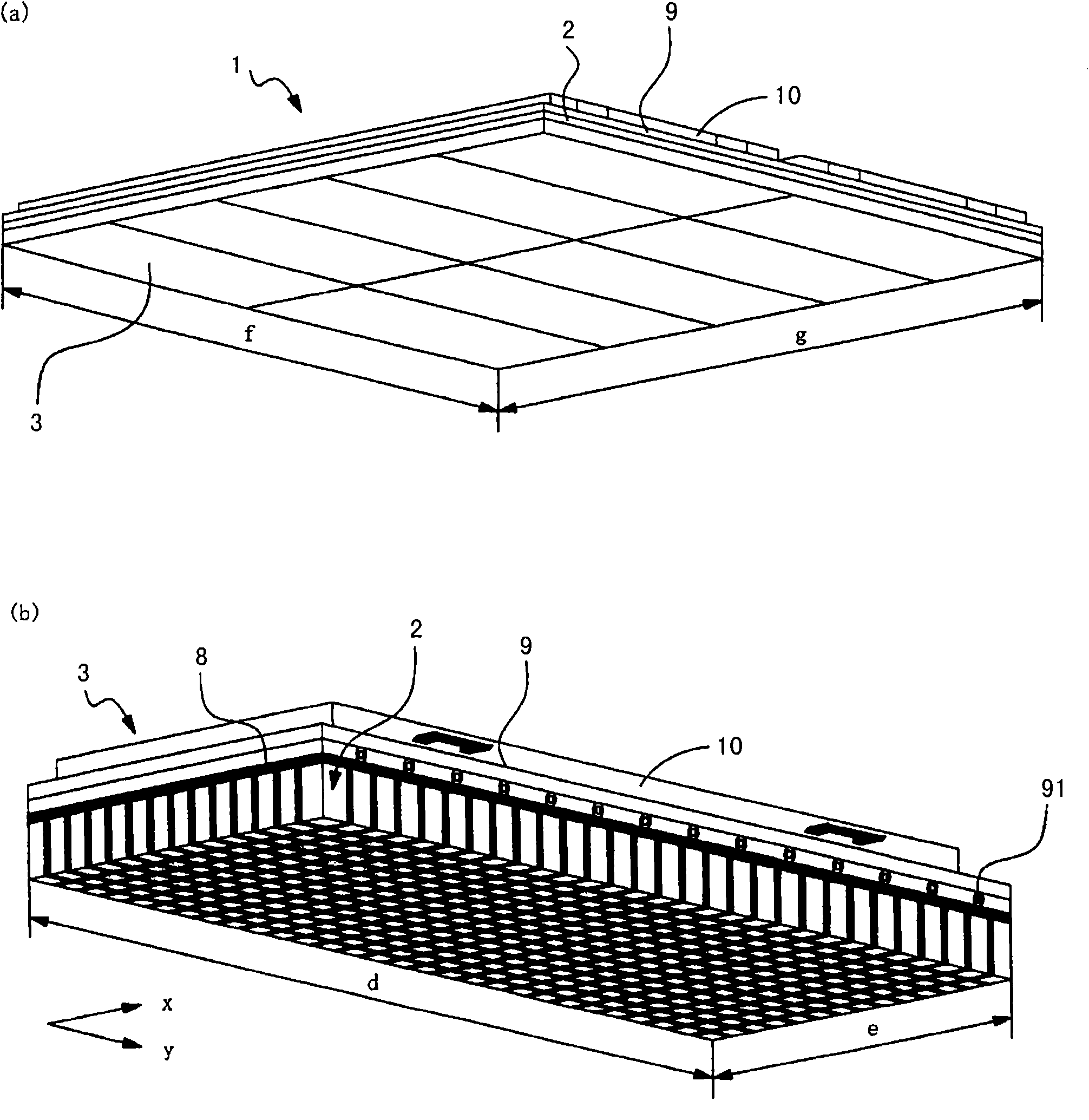
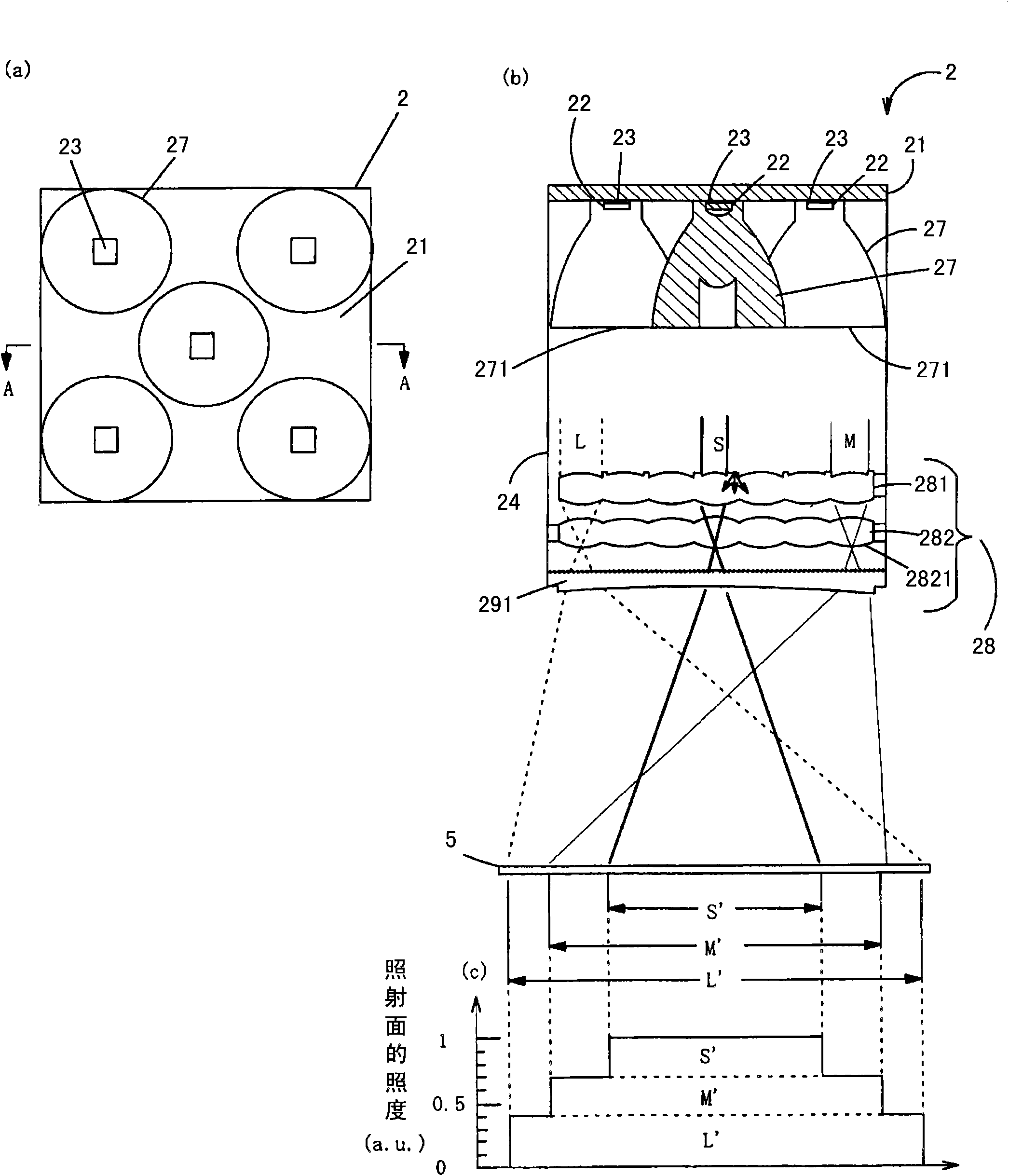
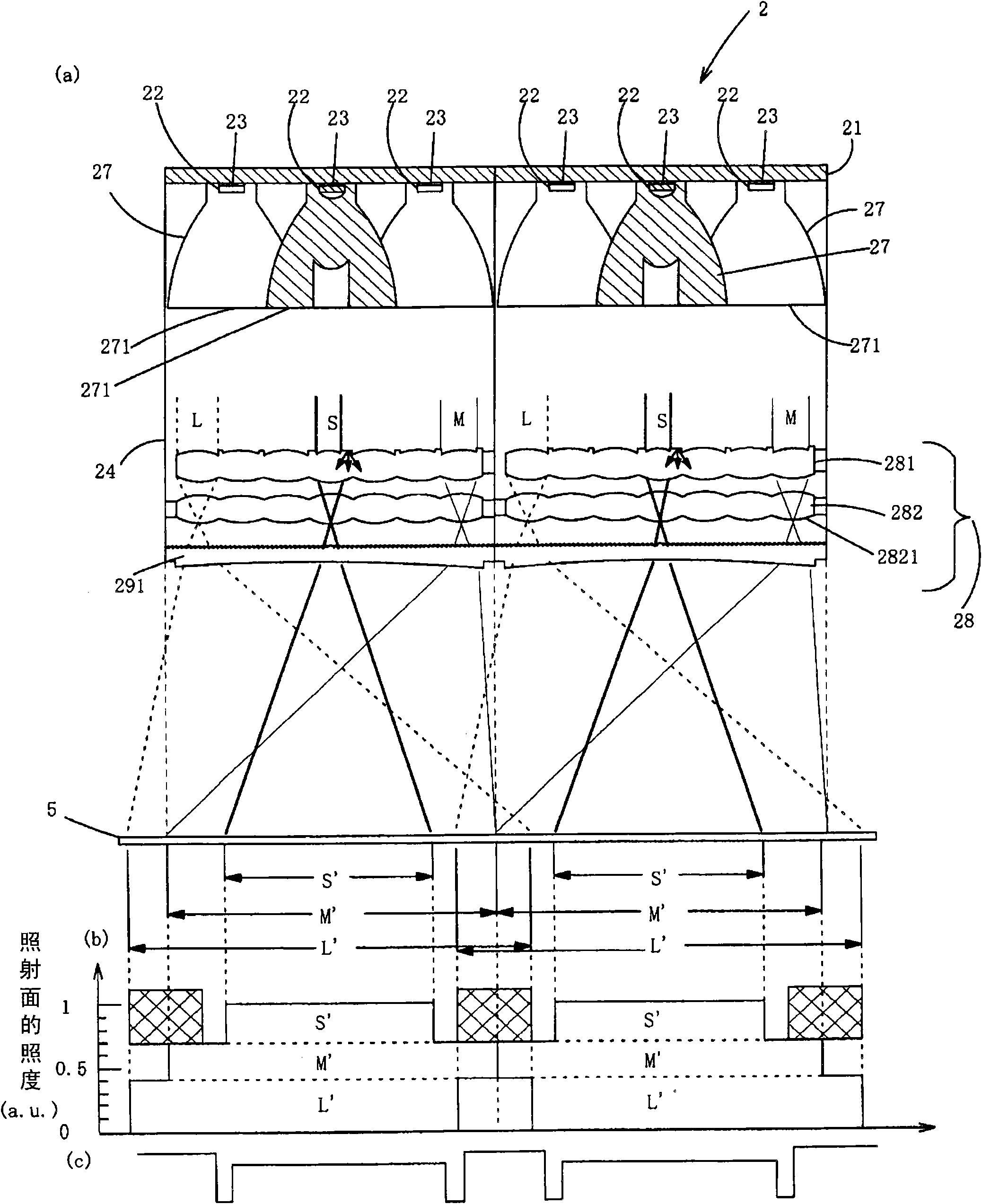
The present invention provides a light irradiation device using a LED, which can suppress peaks of the added-up light quantities and to make it possible to render the distribution of the irradiance at the surface to be irradiated uniform. The light irradiation device comprises: a plurality of adjacently arranged segment light sources, wherein said segment light source comprises an integrator lens arranged such as to be irradiated with light of said plurality of LEDs and a condenser lens, wherein the light from the LEDs is irradiated on the irradiation surface of the workpiece (5). The integrator lens consistes of a plurality of cell lenses, whose aperture sizes at that side of said integrator lens that opposes said LEDs have different dimensions S, M, L and the irradiance distribution at the surface to be irradiated by each segment light source is rendered such that the irradiance becomes highest at the central positions and the irradiance decreases gradually from the center towards the outer edges. When such segment light sources are arranged adjacent to each other, the regions in which two segment light sources overlap become such that regions with a low irradiance overlap and peaks of added-up light quantities between segment light sources can be suppressed.
Description
technical field [0001] The present invention relates to a light irradiation device, and more particularly to a light irradiation device in which a linear or planar light source including a plurality of LEDs is formed. Background technique [0002] As a light irradiation device including LEDs, for example, Patent Document 1 describes an ultraviolet irradiation device in which a plurality of LEDs are arranged in a row on a substrate. In this device, LED elements are spread over the entire surface of a large-area substrate corresponding to the largest size of a liquid crystal panel substrate, and only the LEDs necessary for curing the predetermined sealant are lit and irradiated. [0003] In addition, Patent Document 2 describes an exposure apparatus in which a light emitting diode is arranged on the same substrate and irradiates light to a workpiece such as a substrate directly below it, similarly to the above. [0004] Figure 16 It is a conceptual diagram of a light irradia...
Claims
Application Information
Patent Timeline
Application Date:The date an application was filed.
Publication Date:The date a patent or application was officially published.
First Publication Date:The earliest publication date of a patent with the same application number.
Issue Date:Publication date of the patent grant document.
PCT Entry Date:The Entry date of PCT National Phase.
Estimated Expiry Date:The statutory expiry date of a patent right according to the Patent Law, and it is the longest term of protection that the patent right can achieve without the termination of the patent right due to other reasons(Term extension factor has been taken into account ).
Invalid Date:Actual expiry date is based on effective date or publication date of legal transaction data of invalid patent.

