Projection display

A display device and projection technology, applied in the direction of using projection device image reproducer, projection device, optics, etc., can solve the problems of inability to obtain contrast, uneven illumination, etc.

Active Publication Date: 2008-12-10
SEIKO EPSON CORP
View PDF1 Cites 2 Cited by
  • Summary
  • Abstract
  • Description
  • Claims
  • Application Information

AI Technical Summary

Problems solved by technology

[0005] In Patent Document 1, when the shape of the front end of the shading plate has a rectangular surface in the direction perpendicular to the shading plate, in the vicinity of the first lens array, when the front end of the shading plate is located in the second lens array in the direction of rotation of the shading plate When the center of curvature of the shading plate is at the center of the curvature, the rectangular surface of the shading plate is imaged on the light valve, so there is a problem of linear uneven illuminance in the direction of rotation on the light valve and in the direction perpendicular to the direction of the optical axis.
In addition, depending on the shape of the tip of the shade, there is also a problem that sufficient contrast cannot be obtained.

Method used


Image

  • Projection display
  • Projection display
  • Projection display

Examples


Embodiment approach 1

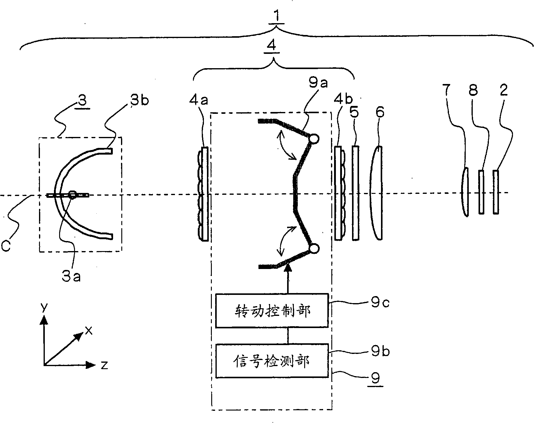
[0049] figure 1 It is a configuration diagram of the illumination optical system 1 of the projection display device according to Embodiment 1 of the present invention. Such as figure 1 As shown, the illumination optical system 1 is composed of an integrating lens 4 , a polarization conversion element 5 , a condenser lens 6 , a field lens 7 and a polarizer 8 located between the light source system 3 and the light valve 2 . In addition, the projection display device according to Embodiment 1 of the present invention has a projection lens (not shown) for projecting the light emitted from the light valve 2 onto a screen. In addition, the light valves 2 are arranged on the respective optical paths of RGB, figure 1 The illustrated illumination optical system 1 representatively shows one of the respective optical paths of RGB.

[0050]The light valve 2 uses a liquid crystal light valve in the embodiment of the present invention, but when a lens array is used, it may be a DMD (Digi...

Embodiment approach 2

[0086] Figure 20 It is a configuration diagram of the illumination optical system 1b of the projection display device according to Embodiment 2 of the present invention. In Embodiment 2 of this invention, it is characterized in that the front-end|tip part of the light-shielding bodies 9T and 9B of the rotation mechanism 9a is formed in the shape of a blade. The configuration and operation of the other parts are the same as those of Embodiment 1, and therefore description thereof will be omitted here.

[0087] Figure 21 It is a diagram showing the rotational position of the rotational mechanism when an image is formed on the light valve according to Embodiment 2 of the present invention. Portions corresponding to Embodiment 1 are given the same reference numerals. Figure 22 The configuration positions of the light-shielding bodies 9T and 9B in Figure 15 same. In addition, 210, 211, 220, and 221 all represent axes passing through the center of curvature of the second le...

Embodiment approach 3

[0093] Figure 26 It is a configuration diagram of an illumination optical system 1 c of a projection display device according to Embodiment 3 of the present invention. Embodiment 3 of the present invention is characterized in that the front ends of the light-shielding bodies 9T and 9B are shaped to have a small opening area, so that the contrast can be sufficiently improved without causing uneven illumination on the light valve 2 . The configuration and operation of the other parts are the same as those of Embodiment 1, and therefore description thereof will be omitted here.

[0094] The light 270 emitted from the second lens array 4b enters the light valve 2 at a relatively large incident angle. At this time, according to the characteristics of the light valve, as the angle of light incident on the light valve 2 increases, the contrast decreases (see Figure 29 ), so it is preferable that the shapes of the light shielding bodies 9T and 9B can shield the light with a relati...


PUM


Abstract

The invention provides a projection display that achieves continuous light amount control with ease and without causing unevenness of illumination of light applied to a light valve responsive to a video signal, thereby allowing constant image display with satisfactory contrast. The projection display of the invention includes a light valve (2); a light source (3a) generating light applied to the light valve (2); an integrator lens (4) provided on an optical path between the light source (3a) and the light valve (2) and making uniform the illumination distribution of light applied from the light source (3a) to the light valve (2); and a light amount control system (9) provided on the optical path and including a turning mechanism (9a) which turns like a set of double doors in order to adjust the amount of light applied from the light source (3a) to the light valve (2). The turning mechanism (9a) is bent into a V shape in a direction to reduce the amount of light (to block the light).

Description

technical field [0001] The present invention relates to a projection display device having a light quantity adjustment mechanism for adjusting the light quantity of light irradiated on a light valve according to a video signal. Background technique [0002] In a projection display device, there is a darker image display due to light leakage from various optical elements constituting the optical system, such as a guide optical system and a projection lens, and stray light (unwanted light) generated at the optical elements. Not dark enough to get a higher contrast tendency. Especially when an image is projected on a screen in a dark room, if the dark image cannot be displayed dark enough, it will give the viewer the impression that the contrast is insufficient. In particular, in projection display devices using liquid crystal light valves, the liquid crystal light valves block transmitted light due to the polarization characteristics of light, but cannot completely block tran...

Claims


Application Information

Patent Timeline
IPC IPC(8): G03B21/14H04N9/31
CPCH04N9/3152G03B21/14
Inventor 山田旭洋别所智宏大上户晃高桥素男
Owner SEIKO EPSON CORP
Why Eureka
Try Eureka