Illumination Device, Light Irradiation Apparatus Using the Same, and Method for Producing Photoreaction Product Sheet with the Apparatus

a technology of light irradiation apparatus and product sheet, which is applied in the direction of lighting and heating apparatus, lighting applications, furniture, etc., can solve the problems of increasing power consumption, reducing the efficiency of cylindrical light sources, and increasing the quantity of heat, so as to reduce the number of light sources and uniform illumination. , the effect of reducing the manufacturing cost of equipment per s

Inactive Publication Date: 2008-11-06
NITTO DENKO CORP
View PDF8 Cites 4 Cited by
  • Summary
  • Abstract
  • Description
  • Claims
  • Application Information

AI Technical Summary

Benefits of technology

[0020]By means of employing the illumination device, uniform illuminance distribution can be obtained over a wide range. Accordingly, a photoreactive composition having a uniform property can be formed. Furthermore, since uniform illuminance distribution can be obtained over a wide range, illumination devices can be arranged with gaps therebetween, thereby enabling a reduction in the number of light sources when compared to that of conventional light irradiation apparatus. Therefore, not only manufacturing cost of the equipment per se, but also running cost of the equipment can be lowered. Consequently, manufacturing cost of a photoreaction product sheet, such as an adhesive tape, which is an end product, can also be lowered.

Problems solved by technology

Consequently, a considerable number of illumination devices are used, whereby power consumption is increased, along with a quantity of heat from the illumination devices.
Therefore, since light must be attenuated by use of a filter or the like, rendering the cylindrical light source extremely energy-inefficient.

Method used


Image

  • Illumination Device, Light Irradiation Apparatus Using the Same, and Method for Producing Photoreaction Product Sheet with the Apparatus
  • Illumination Device, Light Irradiation Apparatus Using the Same, and Method for Producing Photoreaction Product Sheet with the Apparatus
  • Illumination Device, Light Irradiation Apparatus Using the Same, and Method for Producing Photoreaction Product Sheet with the Apparatus

Examples


example 1

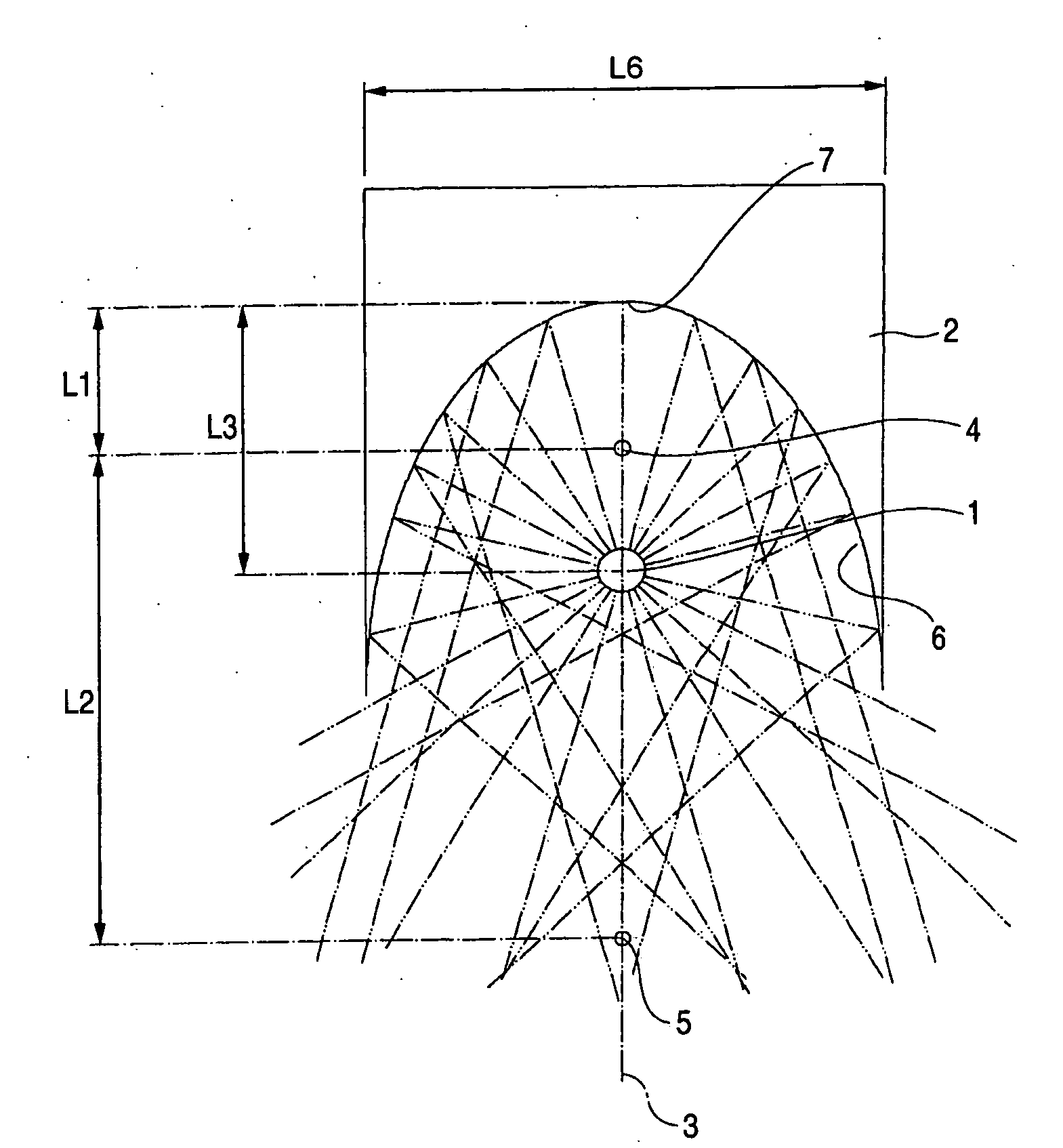
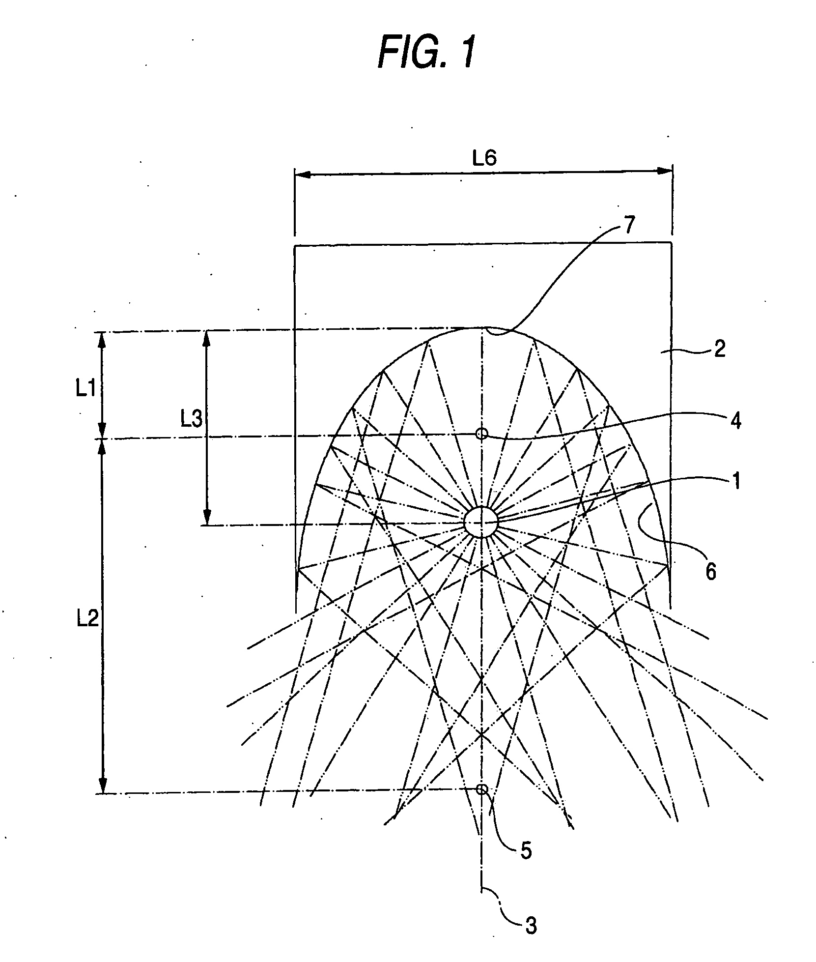
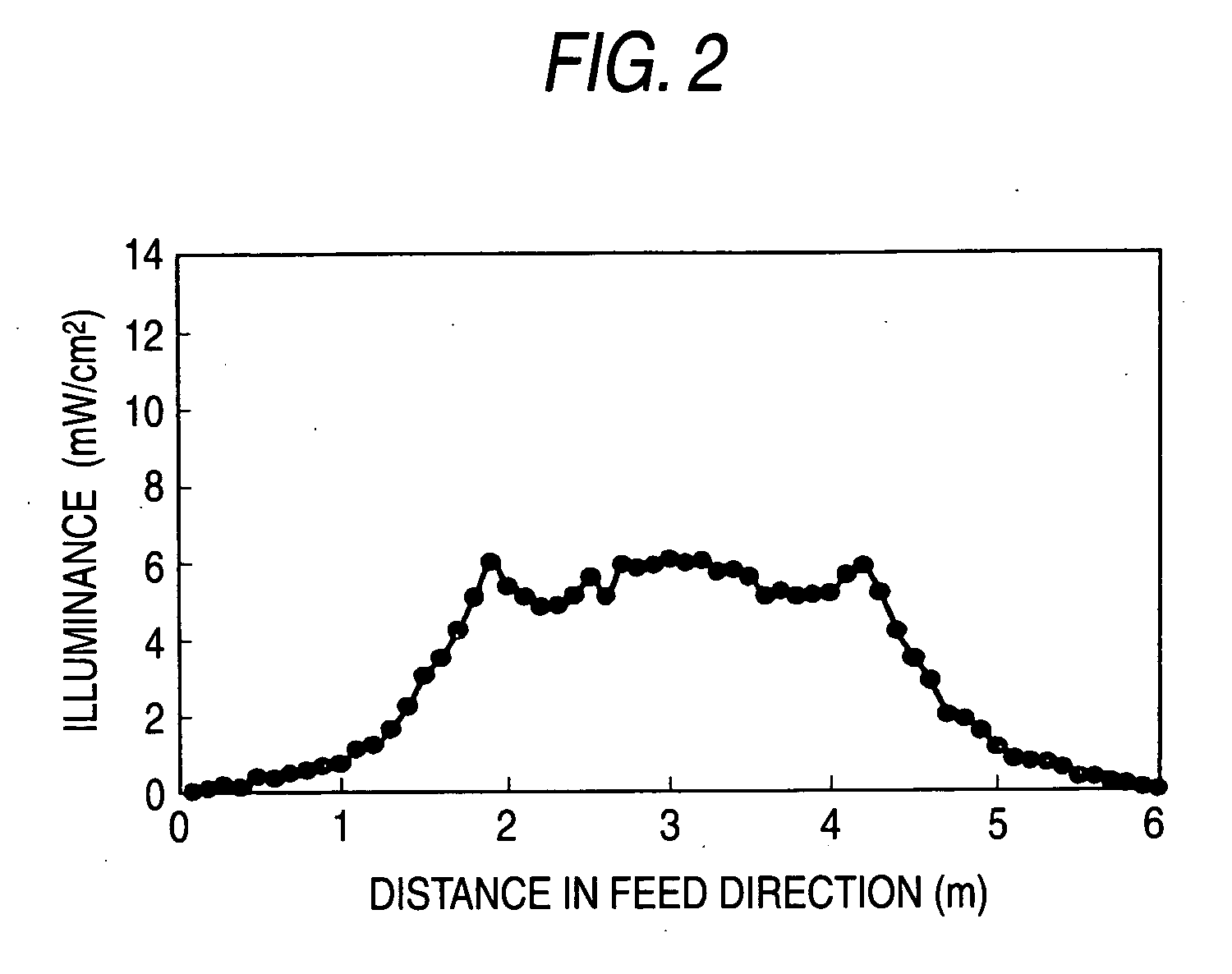
[0050]As a subject to be radiated, a PET sheet (manufactured by TORAY Industries, Inc., Lumirror S10) was set; and a high-pressure mercury lamp (120 W / cm; emission length 250 mm) was disposed at a location of 1 m from the subject as the cylindrical light source. The light source was set such that the direction of the reference axis is perpendicular to the feed direction of the sheet. An elliptic curved mirror, in which a distance between the first focal point and the bottom point of the curved mirror was 20 mm, a distance between the first and second focal points was 150 mm, and a distance between the light source center and the bottom point of the curved mirror was 60 mm, was set. The curved mirror was 117 mm in width. Measurement of illuminance on the PET sheet, with illuminance meter UVR-T1 (manufactured by TOPCON CORPORATION; light receiver unit UD-T36; measurement wavelength 300 to 390 nm; peak-sensitive wavelength 350 nm), showed that a length of the irradiated region (in a fe...

example 2

[0051]A curved mirror of a parabola shape, in which a distance between the bottom point of the curved mirror and the focal point was 100 mm, a distance between the light source center and the bottom point of the curved mirror was 20 mm, and the width of the curved mirror was 200 mm was set. In all other respects, the experimental condition was rendered analogous to that of Example 1. Measurement of illuminance on the PET sheet showed that a length of the irradiated region (in a feed direction of sheet) where the variation in illuminance falls within ±1 mW / cm2 was 2,300 mm.


PUM

PropertyMeasurementUnit
distance L1aaaaaaaaaa
distance L2aaaaaaaaaa
distance L3aaaaaaaaaa

Abstract

The present invention provides an illumination device including a cylindrical light source and a curved mirror for reflecting light radiated from the cylindrical light source, wherein the curved mirror has a light reflection surface which has a shape of a portion of an elliptic curve having a first focal point and a second focal point on a reference axis of the curved surface, in a cross-sectional surface perpendicular to the axial direction of the light source, and the cylindrical light source is disposed on the reference axis at a position between the first focal point and the second focal point, a light irradiation apparatus including the illumination device, and a method for producing a photoreaction product sheet using the irradiation apparatus.

Description

FIELD OF THE INVENTION[0001]The present invention relates to an illumination device for effectively radiating light so as to attain uniform illuminance distribution over a wide range. In particular, the present invention relates to an illumination device for use in photo-polymerization for forming an adhesive layer during a manufacturing process of an adhesive tape, and light irradiation apparatus using the same.BACKGROUND ART[0002]As a method for manufacturing a photoreaction product sheet, such as an adhesive tape, the following method is known. That is, a substrate of, e.g., a filmshape, is coated to form a photoreactive composition layer of an appropriate thickness, and the thus-applied photoreactive composition layer is caused to react by means of light irradiation with a light irradiation apparatus, thereby forming a photoreaction product layer. In many cases, light irradiation apparatus of this type employs cylindrical light sources as light sources, which are, in many cases,...

Claims


Application Information

Patent Timeline
Patent Type & Authority Applications(United States)
IPC IPC(8): F21V7/00B29D7/01B01J19/12F21S2/00F21V7/08F21V13/00F21Y103/00F26B3/28
CPCF26B3/28F21V7/08F26B3/286F21Y2103/00F21W2131/40
Inventor HIROSE, ISAO
Owner NITTO DENKO CORP
Why Eureka
Try Eureka