Optical module and light source module

An optical module and light source cavity technology, applied in the field of lighting, can solve the problems affecting the lighting effect, uneven illuminance distribution, secondary light spots, etc., and achieve the effect of eliminating secondary light spots, uniform illuminance distribution, and improving lighting effects.

Pending Publication Date: 2019-01-22
SUZHOU OPPLE LIGHTING +1
View PDF16 Cites 3 Cited by
  • Summary
  • Abstract
  • Description
  • Claims
  • Application Information

AI Technical Summary

Problems solved by technology

[0003] There are many methods of concentrating light beams in the related art. However, usually the way of concentrating light beams can only simply gather the light originally irradiated to other areas in key areas, but it will lead to uneven distribution of illuminance in key areas, resulting in relatively Obvious secondary facula, affecting the lighting effect

Method used


Image

  • Optical module and light source module
  • Optical module and light source module

Examples


Embodiment Construction

[0028] In order to make the purpose, technical solution and advantages of the present application clearer, the technical solution of the present application will be clearly and completely described below in conjunction with specific embodiments of the present application and corresponding drawings. Apparently, the described embodiments are only some of the embodiments of the present application, rather than all the embodiments. Based on the embodiments in this application, all other embodiments obtained by persons of ordinary skill in the art without making creative efforts belong to the scope of protection of this application.

[0029] The technical solutions provided by various embodiments of the present application will be described in detail below in conjunction with the accompanying drawings.

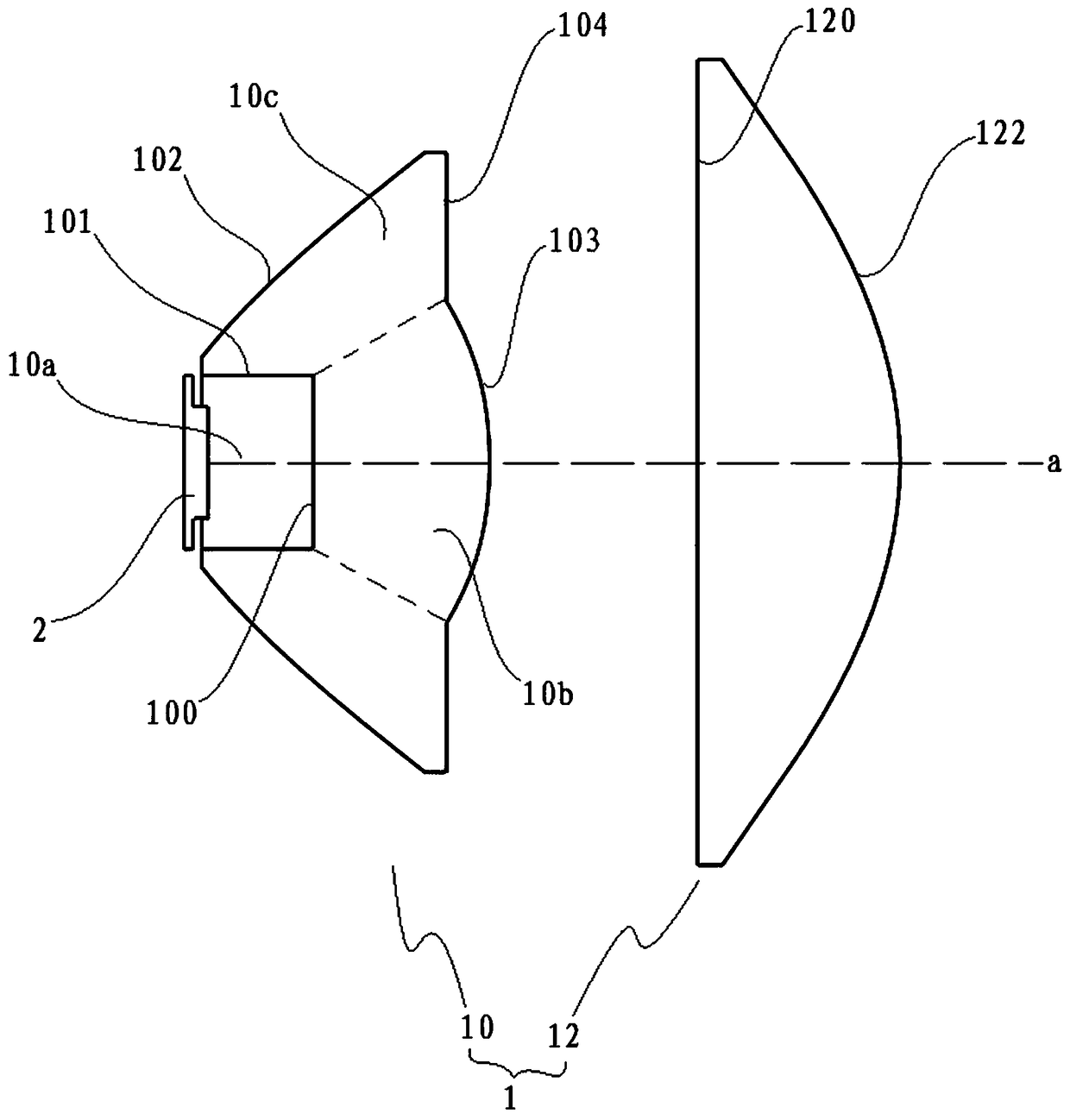
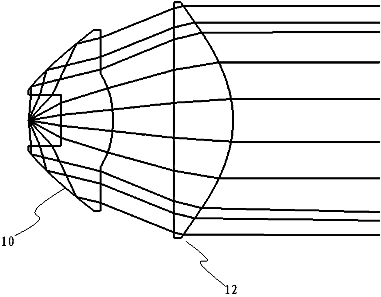
[0030] The embodiment of the present application discloses a light source module, such as figure 1 As shown, it includes an optical module 1 and an LED lamp bead 2 , the LED lamp ...


PUM


Abstract

The application discloses an optical module and a light source module. The optical module includes a total internal reflector and a convex lens; the convex lens is positioned in front of the total internal reflector along the optical axis; the total internal reflector includes a light source cavity; the light source cavity is used for covering an LED; the total internal reflector is used for converging light entering from the light source cavity and casting the light into the convex lens; the convex lens is used for collimating light that enters the total internal reflector. The light source module includes the LED and the optical module; the LED is covered by the light source cavity. The optical module and the light source module disclosed in the embodiment enable illuminance in a key area to be more evenly distributed, side spots can be effectively eliminated, and lighting effect is improved.

Description

technical field [0001] The present application relates to the field of lighting technology, in particular to an optical module and a light source module. Background technique [0002] The use of LEDs in lighting fixtures has begun to gain popularity. Since lighting fixtures have various application occasions, there are also different requirements for the performance of lighting fixtures. For example, for the lighting of key areas, LED lamps are required to gather the emitted light in the key areas, but due to the large luminous angle of LEDs, only part of the light can reach the key areas under normal circumstances, and LED lamps are required to control the light. Light distribution, the light that is originally irradiated to other areas is also concentrated in key areas. [0003] There are many methods of concentrating light beams in the related art. However, usually the way of concentrating light beams can only simply gather the light originally irradiated to other areas...

Claims


Application Information

Patent Timeline
Patent Type & Authority Applications(China)
IPC IPC(8): F21S8/00F21V5/04F21V7/00F21Y115/10
CPCF21S8/00F21V5/04F21V7/00F21Y2115/10
Inventor 王万林
Owner SUZHOU OPPLE LIGHTING
Why Eureka
Try Eureka