Brightness enhancement film and backlight module

A technology of backlight module and enhancement film, which is applied in the directions of optics, nonlinear optics, lighting devices, etc., can solve the problems of difficulty in designing concepts and adapting to electronic devices at the same time, and changes in the range of light output angles, so as to achieve simplified procedures, uniform illumination distribution, and uniform surface The effect of the light source

Inactive Publication Date: 2010-12-29
CORETRONIC
View PDF1 Cites 2 Cited by
  • Summary
  • Abstract
  • Description
  • Claims
  • Application Information

AI Technical Summary

Problems solved by technology

However, since liquid crystal displays on different electronic devices (such as mobile phones, notebook computers, monitors, televisions, etc.) have different requirements for brightness distribution in different directions and different viewing angles, the optical film structure of the above two patents is adopted It is difficult for the backlight module to make the light output angle range change with the change of direction, so this design concept is difficult to apply to various types of electronic devices at the same time

Method used


Image

  • Brightness enhancement film and backlight module
  • Brightness enhancement film and backlight module
  • Brightness enhancement film and backlight module

Examples


Embodiment Construction

[0050]The following descriptions of various embodiments refer to the accompanying drawings to illustrate specific embodiments in which the present invention can be practiced. The direction terms mentioned in the present invention, such as "up", "down", "front", "rear", "left", "right", etc., are only referring to the directions of the drawings. Accordingly, the directional terms are used to illustrate, not to limit, the invention.

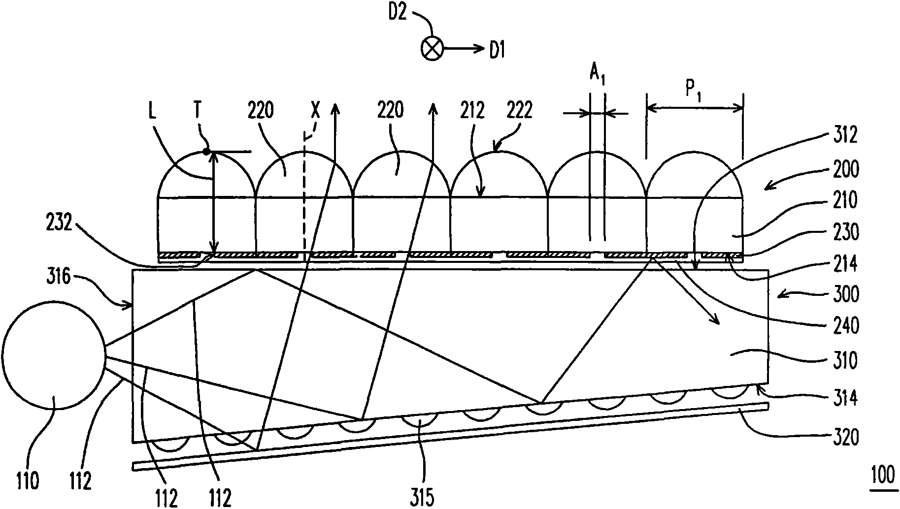
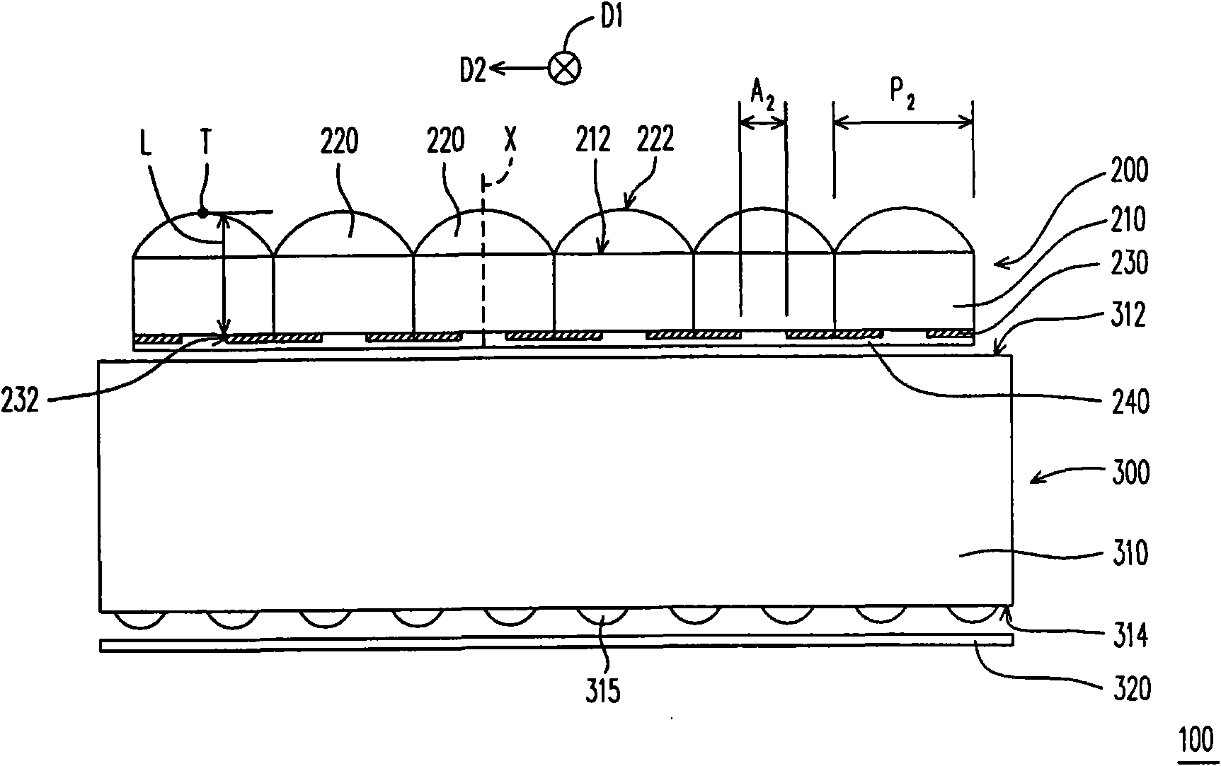
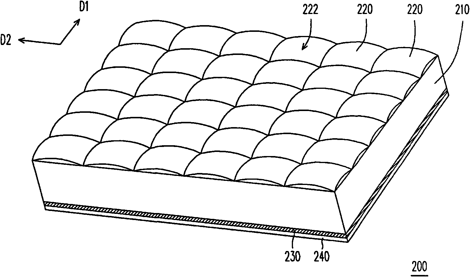
[0051] Figure 1A and Figure 1B It is a schematic cross-sectional view of a backlight module in two mutually perpendicular directions according to an embodiment of the present invention, Figure 2A for Figure 1A The three-dimensional schematic diagram of the enhancement sheet in , while Figure 2B for Figure 2A The schematic diagram of the top view of the enhancement sheet. refer to Figure 1A , Figure 1B , Figure 2A and Figure 2B , the backlight module 100 of this embodiment includes a light emitting element 110 , an enhancement sheet...


PUM

PropertyMeasurementUnit
refractive indexaaaaaaaaaa

Abstract

The invention discloses a brightness enhancement film and a backlight module. The brightness enhancement film comprises a light transmission substrate, a plurality of lenses and a reflection layer. The light transmission substrate is provided with a first surface and a second surface which are opposite. The lenses are collocated on the first surface, wherein each lens is provided with a bent convex side back to the light transmission substrate. The curvature radius of the bent convex side in the first direction parallel to the first surface is R1, the curvature radius of the bent convex side in the second direction parallel to the first surface is R2, and the R1 is not equal to the R2. The reflection layer is collocated on the second surface, wherein the reflection layer is provided with a plurality of light transmission open pores, and the light transmission open pores are positioned on the optical axes of the lenses respectively. The distance between the vertex of the bent convex side of the lens and the corresponding light transmission open pore is L, the refractive indexes of the lenses are n, and the brightness enhancement film satisfies the conditions that L is less than nR1/(n-1) and L is less than nR2/(n-1). The backlight module using the brightness enhancement film is also provided.

Description

technical field [0001] The present invention relates to an optical film and a light source module using it, and in particular to a brightness enhancement film (BEF) and a backlight module using it. Background technique [0002] With the advancement of display technology, flat panel displays have become the mainstream of display devices to replace traditional heavy cathode ray tubes (cathode ray tubes, CRTs). Among flat panel displays, a liquid crystal display (LCD) is more popular and popular. The liquid crystal display includes a liquid crystal panel and a backlight module. The liquid crystal panel itself does not emit light, but is used to determine the light transmission rate. Therefore, a backlight module is arranged behind the liquid crystal panel as a plane light source for the liquid crystal panel. The optical quality of the planar light source has a great influence on the display quality of the liquid crystal display. For example, in order to display images correct...

Claims


Application Information

Patent Timeline
Patent Type & Authority Applications(China)
IPC IPC(8): F21V13/04G02F1/1335
Inventor 萧增科李清祥黄文治庄福明刁国栋
Owner CORETRONIC
Why Eureka
Try Eureka