Eureka AIR delivers breakthrough ideas for toughest innovation challenges, trusted by R&D personnel around the world.

Correcting device of ambient light sensor

A technology of ambient light sensor and calibration device, which is applied in the direction of measuring devices, instruments, scientific instruments, etc., can solve the problem that it takes a lot of time to calibrate the ambient light sensor, and achieve the effect of reducing the calibration

Inactive Publication Date: 2010-12-22
AU OPTRONICS CORP
View PDF0 Cites 9 Cited by
  • Summary
  • Abstract
  • Description
  • Claims
  • Application Information

AI Technical Summary

Problems solved by technology

The method of calibrating the ambient light sensor usually requires the ambient light sensor to receive different illuminance, and since each LCD display usually has multiple ambient light sensors, and each ambient light sensor needs to be calibrated, calibrating the ambient light sensor takes a lot of time

Method used


Image

  • Correcting device of ambient light sensor
  • Correcting device of ambient light sensor
  • Correcting device of ambient light sensor

Examples


Embodiment Construction

[0023] In order to further explain the technical means and effects of the present invention to achieve the intended purpose of the invention, the specific implementation, structure, characteristics and effects of the backlight module proposed according to the present invention will be described below in conjunction with the accompanying drawings and preferred embodiments. The details are as follows.

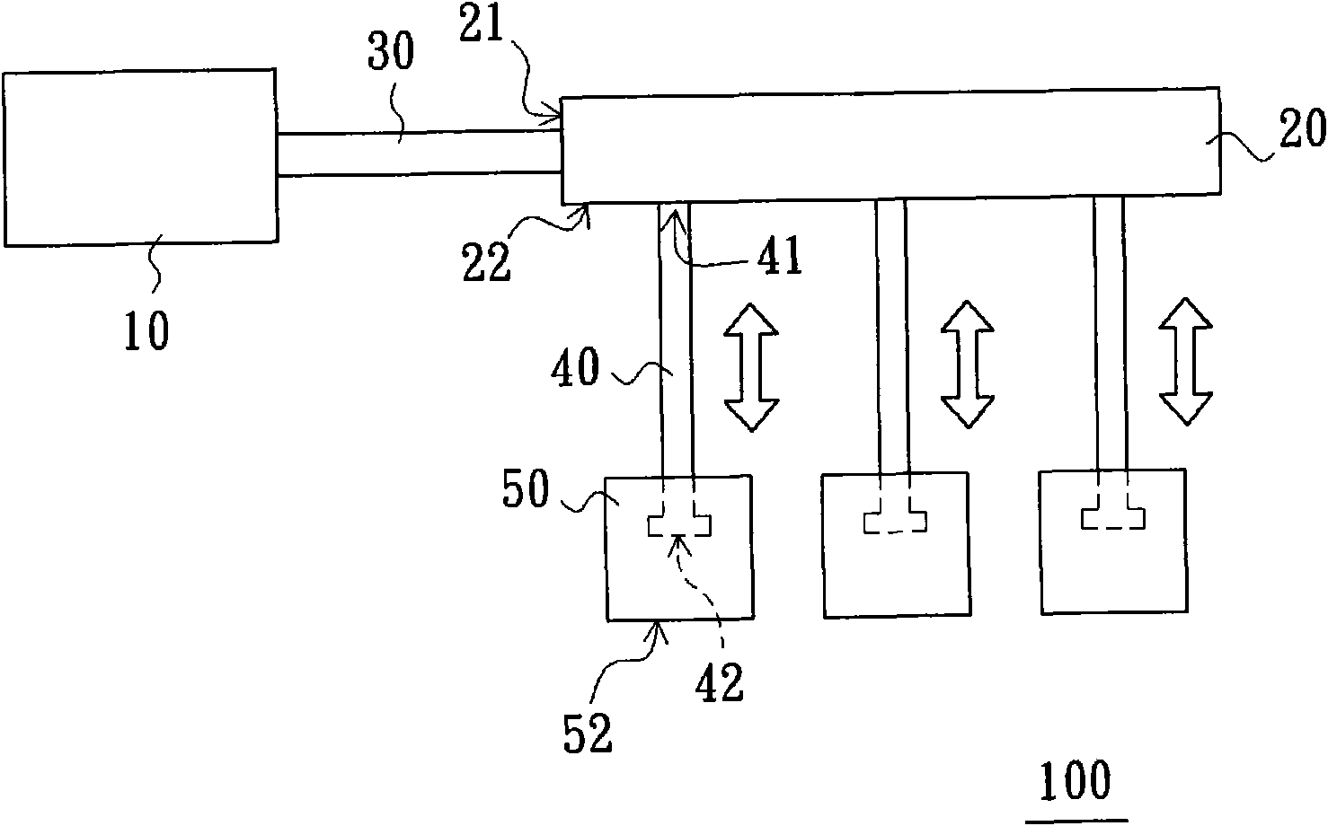
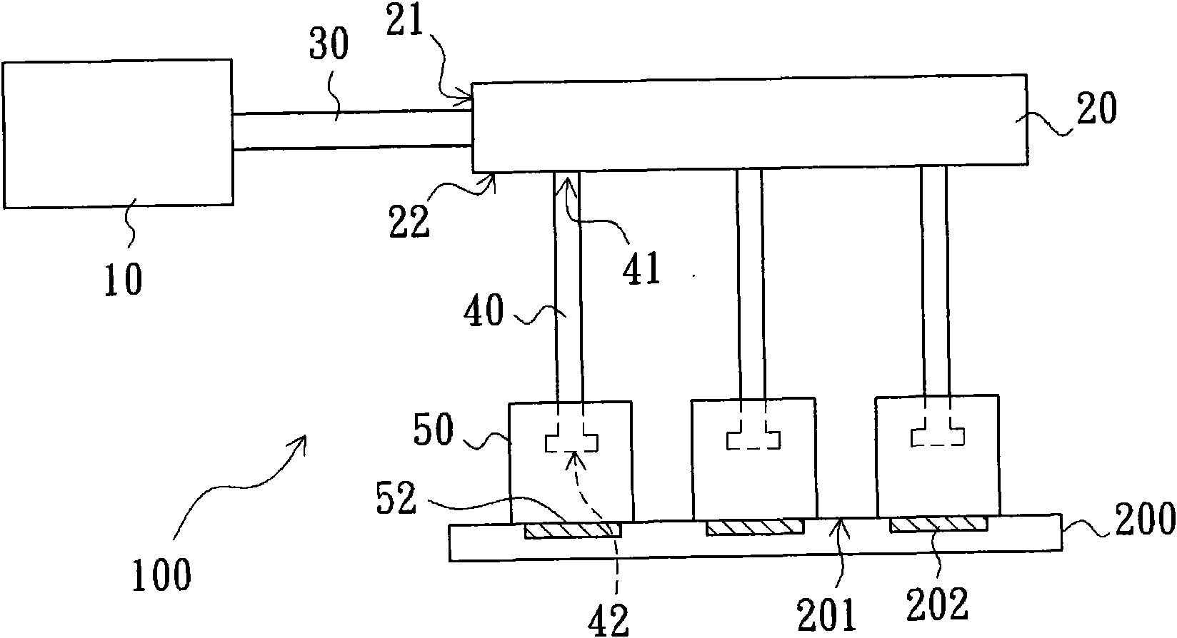
[0024] refer to figure 1 The ambient light sensor correction device 100 provided by the embodiment of the technical solution includes a light source 10, a beam splitter 20, a first light guide 30, at least one second light guide 40, and at least one fine-tuning device 50, wherein the second light guide The number of tubes 40 corresponds to the number of trimming devices 50 . In this embodiment, the number of second light pipes 40 is the same as the number of fine-tuning devices 50 .

[0025] The light source 10 can be a light emitting diode light source or a laser light source,...


PUM


Abstract

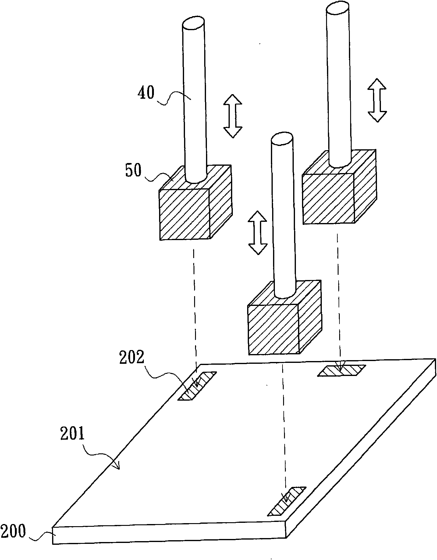
The invention relates to a correcting device of an ambient light sensor, which comprises a light source, an optical splitter, a first light pipe, at least one second light pipe and at least one vernier device, wherein the light source is used for outputting light beams with different illuminance; the optical splitter is provided with an input face and an output face; the two ends of the first light pipe are respectively coupled to the light source and the input face of the optical splitter, and the first light pipe is used for transmitting the light beams emitted by the light source to the optical splitter; each second light pipe comprises an inlet end and an outlet end, and the inlet end of each second light pipe is coupled to the output face of the optical splitter; and the outlet end of each second light pipe can be movably arranged in the corresponding vernier device. The correcting device of the ambient light sensor can reduce the time required for correcting the ambient light sensor.

Description

technical field [0001] The invention relates to a correction device, in particular to a correction device for an ambient light detector. Background technique [0002] Flat-panel displays have been widely used to replace cathode ray tubes and are used in TV or computer screens to become a new generation of display devices. Therefore, the needs of various flat-panel displays, including liquid crystal displays (LCDs), plasma displays (PDPs) ) and organic electroluminescent displays (OLEDs) are rapidly increasing. Among them, liquid crystal displays have a higher penetration rate. [0003] The liquid crystal display mainly includes a liquid crystal display panel and a backlight module. Since the liquid crystal display panel of the liquid crystal display does not emit light, the backlight module needs to be used to provide the display light source required by the liquid crystal display panel. Therefore, the quality of the display light source provided by the backlight module is...

Claims


Application Information

Patent Timeline
Patent Type & Authority Applications(China)
IPC IPC(8): G01J1/00G01J1/04
Inventor 杨家铭赵瑞田林承德涂博翔
Owner AU OPTRONICS CORP
Why Eureka
Eureka Blog
Learn More