DLC (Data Link Control) optical fiber connector assembly and plug thereof

A technology for optical fiber connectors and plugs, which is applied to the field of plugs of the connector assembly, and can solve problems such as inability to achieve fast plugging and unplugging

Active Publication Date: 2012-01-25
CHINA AVIATION OPTICAL-ELECTRICAL TECH CO LTD
View PDF0 Cites 0 Cited by
  • Summary
  • Abstract
  • Description
  • Claims
  • Application Information

AI Technical Summary

Problems solved by technology

[0003] The purpose of the present invention is to provide a DLC optical fiber connector assembly to solve the problem in the prior art that the insertion and separation of the optical fiber connector and the adapter connector need to be carried out in two steps, which cannot realize fast plugging and unplugging

Method used


Image

  • DLC (Data Link Control) optical fiber connector assembly and plug thereof
  • DLC (Data Link Control) optical fiber connector assembly and plug thereof
  • DLC (Data Link Control) optical fiber connector assembly and plug thereof

Examples


Embodiment Construction

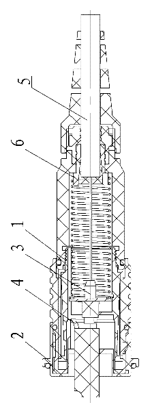
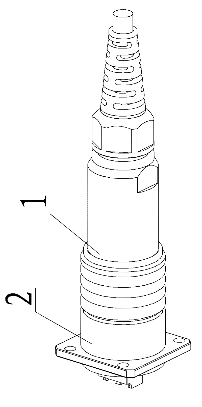
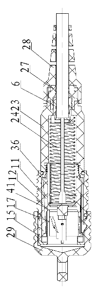
[0030] An embodiment of a DLC fiber optic connector assembly, in figure 1 , figure 2 , the connector assembly, including plug 1 and receptacle 2, is in Figure 3~Figure 13 in, combine figure 1 , figure 2 , the plug includes an internal DLC plug module 3, and the DLC plug module 3 has a duplex clip 4 that is engaged with the adapted DLC socket module, and the duplex clip 4 can be pressed to make the DLC plug module and the matched DLC socket module Separation, the rear end of the DLC plug module has an optical cable 5, and the aramid fiber of the optical cable 5 is fixed on the bonding sleeve 6 by filling glue. The outer peripheral surface of the bonding sleeve 6 is a stepped shaft with a large diameter at the front end and a small diameter at the rear end. The inner hole of the bonding sleeve 6 is for the optical cable 5 to pass through, and the peripheral surface of the inner hole of the bonding sleeve 6 is a tapered surface that flares forward, and the fixing glue for f...


PUM


Abstract

The invention relates to a DLC (Data Link Control) optical fiber connector assembly and a plug thereof. The outer circumferential surface of an inner shell of the plug is provided with an elastic jaw which faces to the front end and is provided with a locking block at the front end head, a DLC plug module can be slidably arranged in an inner hole of the inner shell through a fixed plate fixed onthe DLC plug module, the front end face of the fixed plate is in blocking matching with an inner convex baffle plate of the inner shell, the rear end face of the fixed plate is in elastic matching with a blocking step surface at the rear end of the inner shell through a thrust spring, an outer shell is sleeved on the periphery of the inner shell, the locking block of the elastic jaw is arranged in a locking hole of the outer shell and protrudes out of the outer circumferential surface of the outer shell, the front end of the inner hole of the inner shell is provided with a strip-shaped tonguepiece arranged along the axle line of the inner shell, the outer surface of the strip-shaped tongue piece is attached on the wall of the inner hole of the inner shell, the inner surface of the strip-shaped tongue piece is used for pushing a duplexing clamp of the DLC plug, the strip-shaped tongue piece is fixedly arranged on the outer shell through the front end thereof, and the circumferential surface of the inner hole of the inner shell is provided with a pushing step for pushing the strip-shaped tongue piece to face to the front end when the outer shell drives the strip-shaped tongue pieceto move backwards at the rear end head of the strip-shaped tongue piece.

Description

technical field [0001] The invention relates to an optical fiber connector assembly in which a DLC plug module is arranged in a casing, and simultaneously the invention also relates to a plug of the connector assembly. Background technique [0002] In the field of optical signal transmission, the DLC plug module is widely used. The DLC plug module includes a plug part, and the tail end of the plug part is connected with an optical cable. The DLC plug module can be used to transmit optical signals, but it cannot bear the pulling force from the optical cable. This requires the outer casing of the optical module to form an optical fiber connector, and the aramid fiber of the optical cable is poured on the bonding sleeve. The inner hole of the bonding sleeve is generally a stepped hole or the inner hole wall is a tapered surface. The glue is poured into the flaring end of the inner hole of the bonding sleeve to pour the aramid fiber of the optical cable on the bonding sleeve to ...

Claims


Application Information

Patent Timeline
Patent Type & Authority Patents(China)
IPC IPC(8): G02B6/38
Inventor 方尚杰
Owner CHINA AVIATION OPTICAL-ELECTRICAL TECH CO LTD
Why Eureka
Try Eureka