Inverter controlling apparatus, and air conditioner and washer using the same
What is AI technical title?
AI technical title is built by Patsnap AI team. It summarizes the technical point description of the patent document.
A control device, inverter technology, applied in the direction of output power conversion device, control system, general control strategy, etc.
Active Publication Date: 2014-03-19
HITACHI JOHNSON CONTROLS AIR CONDITIONING INC
View PDF4 Cites 0 Cited by
Summary
Abstract
Description
Claims
Application Information
AI Technical Summary
This helps you quickly interpret patents by identifying the three key elements:
Problems solved by technology
Method used
Benefits of technology
Problems solved by technology
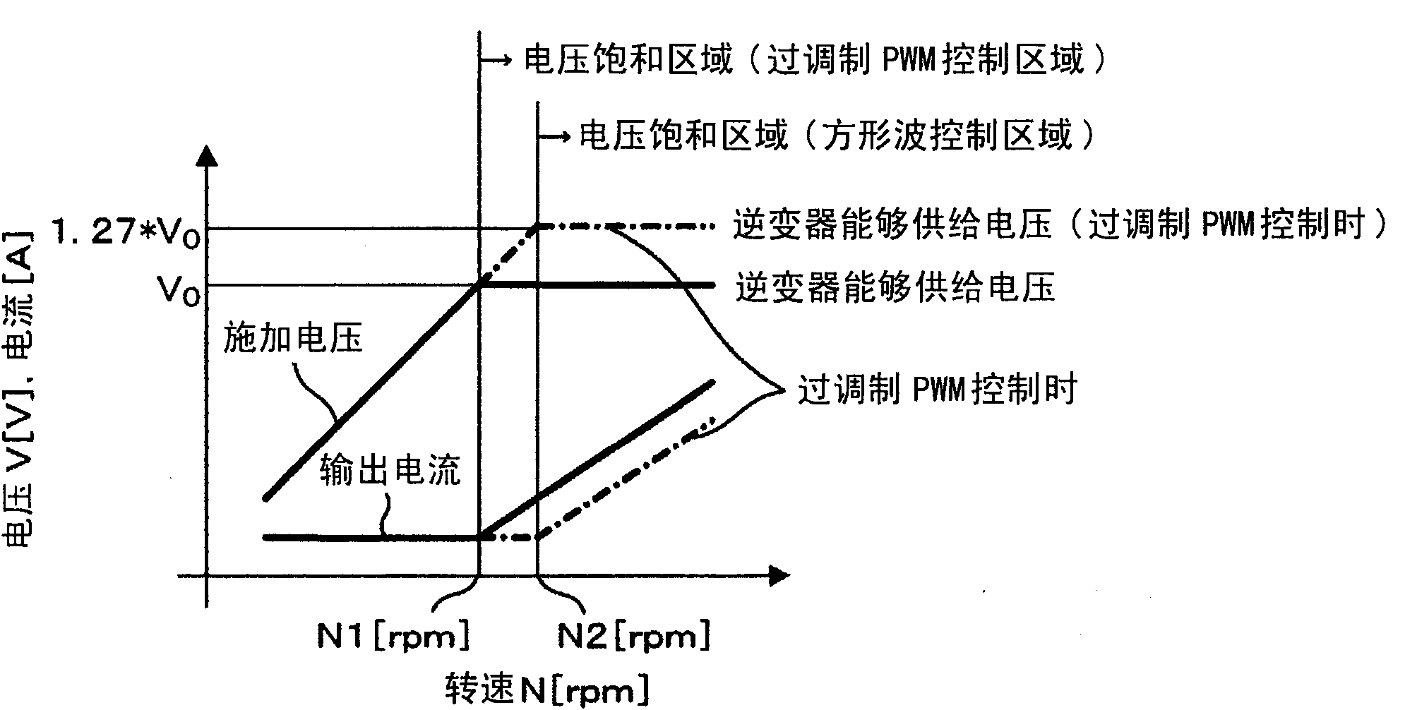
[0024] Therefore, there is a problem that a large amount of ineffective current flows when only the conventional technology and the configuration of field weakening control are used together.
More specifically, there is a problem that control using conventional techniques, overmodulation PWM control, and field weakening control cannot be performed
Method used
Image
Click on the blue label to locate the original text in one second.
Reading with bidirectional positioning of images and text.
Examples
Embodiment 1
[0047] use Figure 3 ~ Figure 6 , the first embodiment of the present invention will be described.
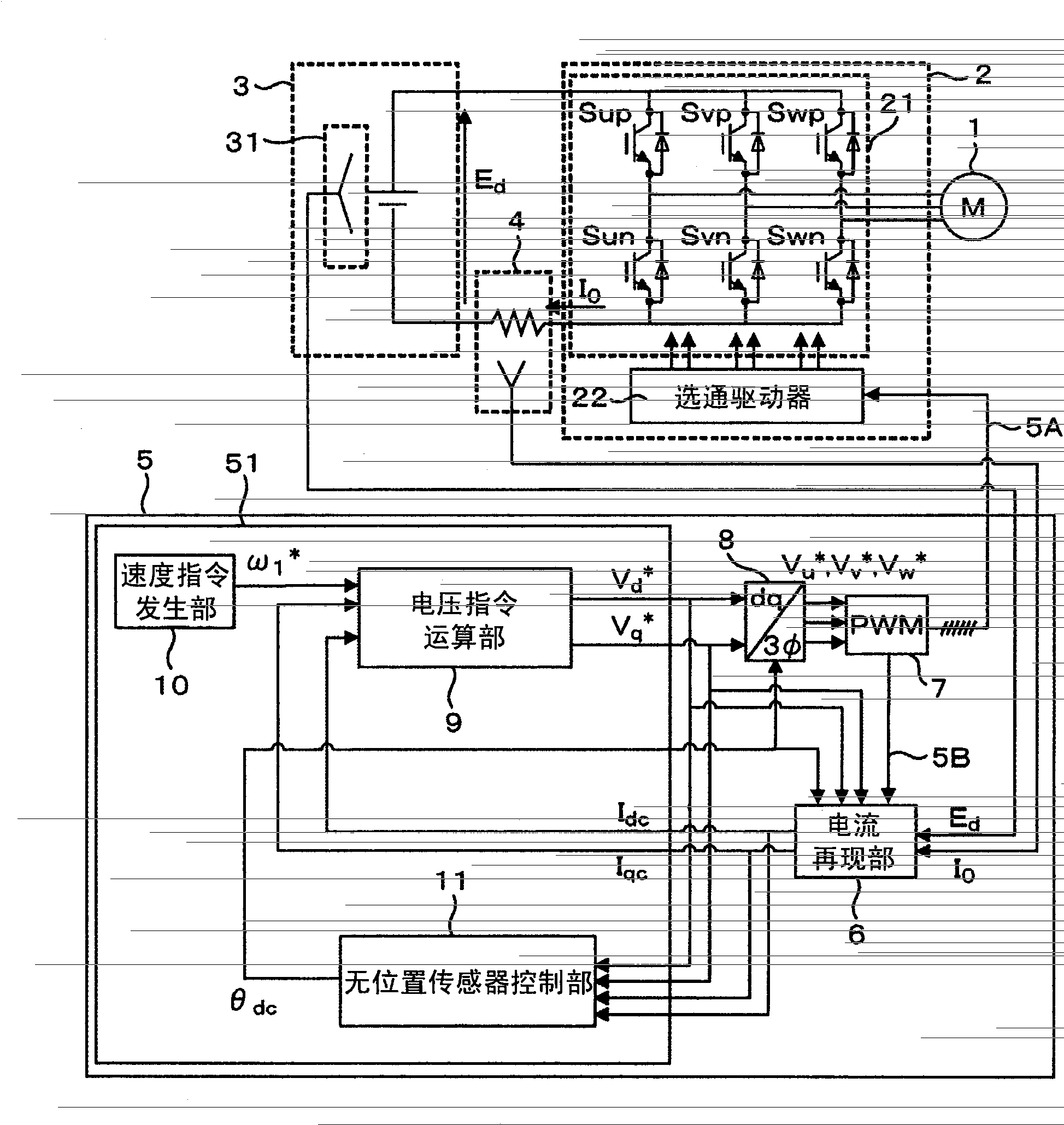
[0048] image 3 shows the configuration of a motor drive device as an embodiment of the present invention, Figure 4 The processing of the current reproduction unit 6 is shown.
[0049] The inverter 2 includes: an inverter main circuit 21 composed of IGBTs and diodes, and a selection device for generating a gate signal applied to the IGBTs of the main circuit according to a pulse width modulation signal (PWM signal) 5A output from the control device 5. through the driver 22; according to the PWM signal 5A, the DC voltage E supplied from the DC power supply 3 d It is converted into a three-phase AC voltage and supplied to the motor 1 .
[0050] The DC bus current detector 4 uses a DC shunt resistor to detect the DC bus current I flowing into the inverter 2 0 , and output it to the control device 5.
[0051] The DC voltage detector 31 detects the DC voltage E applied to the...
Embodiment 2
[0143] use Figure 12 , Figure 13 , the second embodiment in which the motor drive device using the current detection method of the first embodiment is applied to the drive of the stirring blade of the washing machine will be described.
[0144] First, use Figure 12 , the overall configuration of the washing machine will be described.
[0145] The washing machine 200 is composed of an agitating blade 203 for agitating the washing tank, an agitating blade driving motor 202 for driving the agitating blade, a motor driver 201 for controlling the agitating blade driving motor 202, an inner washing tank 204 and an outer washing tank 205 for washing clothes.
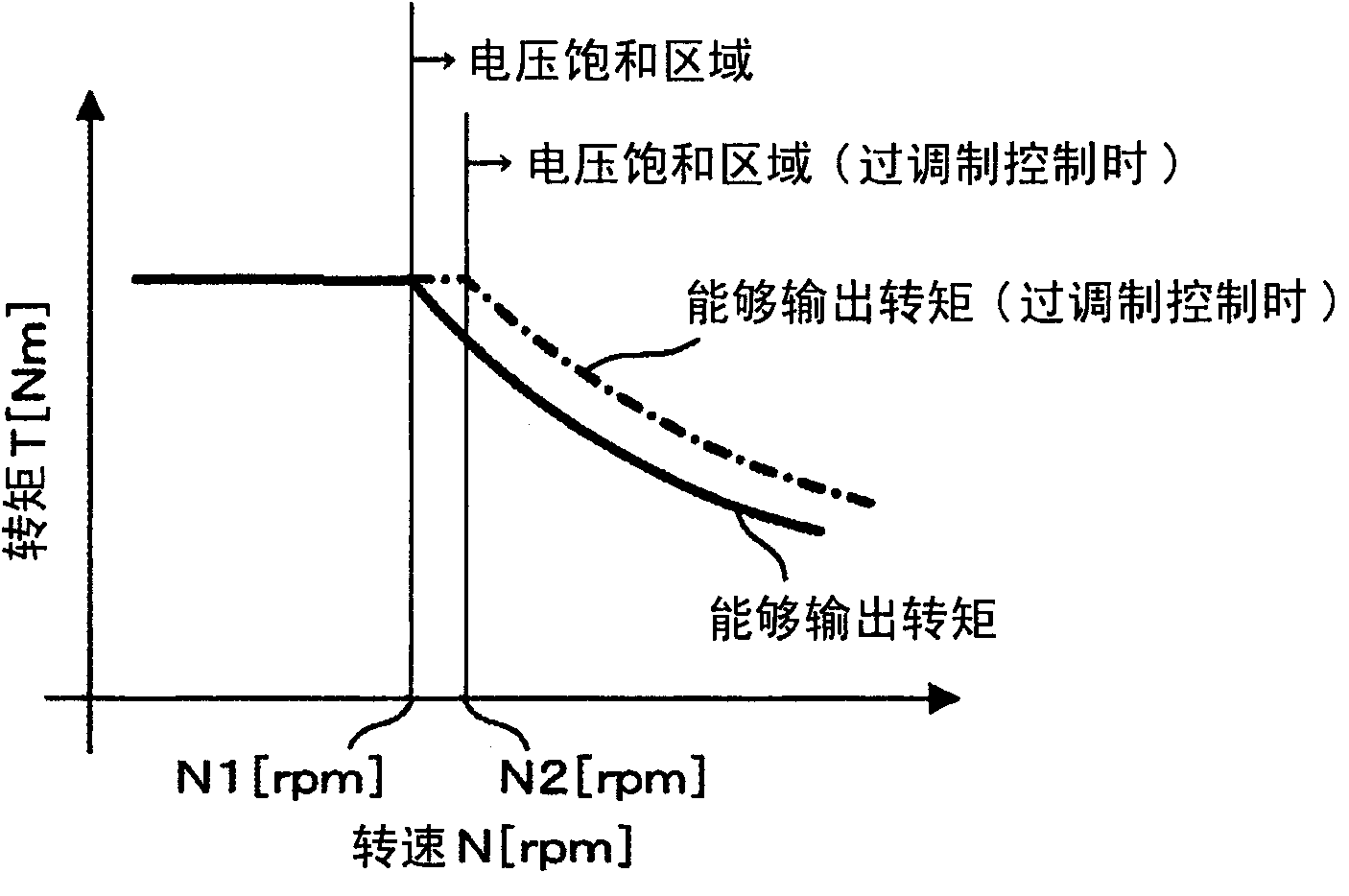
[0146] Here, using a schematic diagram showing the motor speed and torque characteristics showing the operating point of the stirring blade drive motor Figure 13 , the operating point of the stirring blade drive motor 202 will be described.
[0147] The stirring blade drive motor 202 operates at operating point A, which...
PUM
Abstract
Provided is an inverter control apparatus (5) incorporating therein a current reproduction unit (6) which inputs information from a DC-bus current detector 4 for detecting the instantaneous phase currents that flows into an electric motor (1) and that is contained in the DC-bus current flowing into the inverter (2) from a DC power source (3), and which reproduces phase currents that flow into the motor (1) on the basis of the values of the instantaneous phase currents, wherein, in the voltage saturation range, the current production unit (6) calculates the phase currents flowing into the motor (1) on the basis of the average DC-bus current obtained through filtering the DC-bus current and an instantaneous phase current for a single phase; and the voltage commands for the voltages to be applied to the inverter (2) is calculated by using the phase currents.
Description
technical field [0001] The invention relates to a control device of an inverter, in particular to an output current detection method of the inverter and a technology for detecting the output current (phase current) according to the DC bus current. Background technique [0002] Motor drive devices used in air conditioners, washing machines, and the like are strongly required to be small in size, low in cost, high in efficiency, and high in output, and a large number of technologies for realizing these demands have been developed. [0003] To meet the demand for high efficiency of motor drive devices, permanent magnet motors are generally used as motors. However, in order to further increase efficiency, motors are designed to be highly efficient during normal operation (low-speed rotation range) of air conditioners and washing machines. [0004] However, if the motor is designed to achieve high efficiency during low-speed rotation, it will be difficult to achieve high output f...
Claims
Application Information
Patent Timeline
Application Date:The date an application was filed.
Publication Date:The date a patent or application was officially published.
First Publication Date:The earliest publication date of a patent with the same application number.
Issue Date:Publication date of the patent grant document.
PCT Entry Date:The Entry date of PCT National Phase.
Estimated Expiry Date:The statutory expiry date of a patent right according to the Patent Law, and it is the longest term of protection that the patent right can achieve without the termination of the patent right due to other reasons(Term extension factor has been taken into account ).
Invalid Date:Actual expiry date is based on effective date or publication date of legal transaction data of invalid patent.

