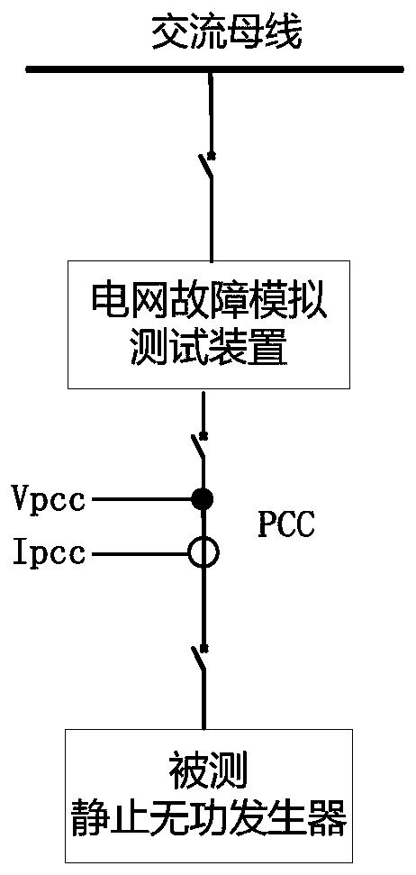
Voltage fault ride-through test method for static var generator
A static reactive power and voltage fault technology, applied in the field of power electronics, can solve the problems of high cost and difficulty in increasing the capacity of the power grid fault simulation test device.
- Summary
- Abstract
- Description
- Claims
- Application Information
AI Technical Summary
Problems solved by technology
Method used
Image
Examples
example 1
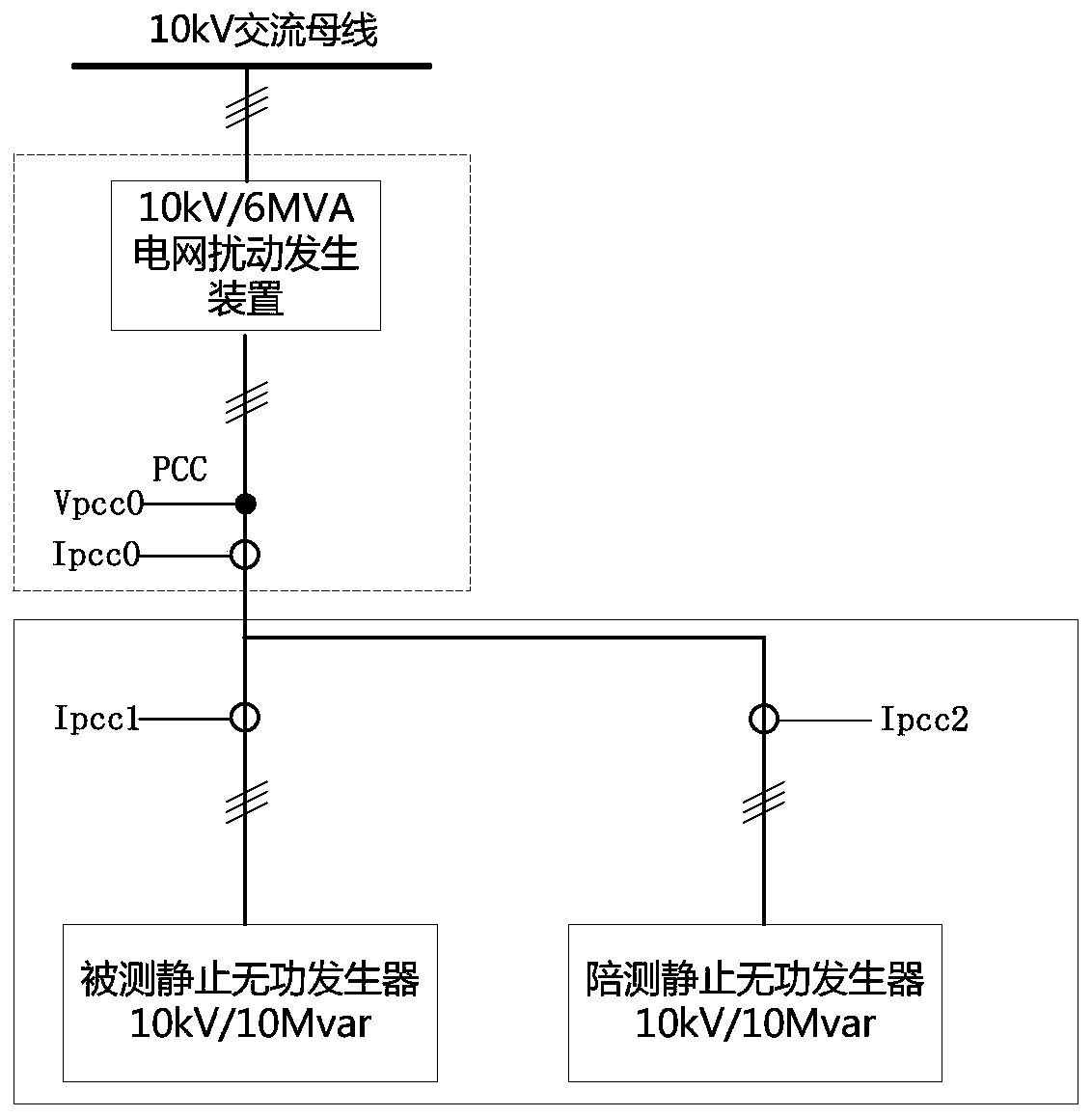
[0033] In this example (such as image 3 As shown), the capacity of the static var generator under test is 10kV / 10Mvar, the capacity of the power grid fault simulation test device is 10kV / 6MVA, the capacity of the grid disturbance generator is smaller than the capacity of the static var generator under test, and the capacity of the power grid fault generator under test When the reactive support current output during the voltage fault ride-through period is greater than the rated current of the grid fault simulation test device, according to the voltage fault ride-through test requirements, it will inevitably cause the grid disturbance generator to over-current and shut down, and the test work cannot be carried out. For example, when the voltage drops to When the rated voltage is 20%, the output reactive current of the grid disturbance generating device is 1.75 times of the rated current. Can adopt the testing method that the present invention proposes now, specifically compris...
example 2
[0044] In this example (such as Figure 4 As shown), the capacity of the static var generator under test is 35kV / 28Mvar, the capacity of the power grid disturbance generating device is 35kV / 10MVA, and the capacity of the power grid disturbance generating device is smaller than the capacity of the measured static var power generator. According to the normal test requirements, the power grid disturbance generating device The capacity must be shut down due to overcurrent, which makes the test work unable to be carried out. Can adopt the testing method that the present invention proposes now, specifically comprise following link:
[0045] Provide a test static var generator, such as 35kV / 20Mvar.
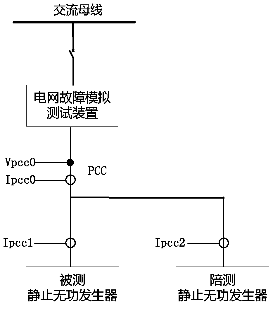
[0046] Connect the static var generator under test and the static var generator under test in parallel to the output terminal of the power grid disturbance generating device.
[0047] Install voltage and current sensors at the output of the power grid disturbance generator to detect Vp...
example 3
[0087] In this example (such as Figure 5As shown), the capacity of the static var generator under test is 35kV / 10Mvar, and the impedance divider device is used to simulate the power grid fault. The capacity of the impedance divider device is 35kV / 6MVA. According to the normal test requirements, the impedance voltage divider will be shut down due to an overcurrent fault, resulting in the inability to carry out the test work. Can adopt the testing method that the present invention proposes now, specifically comprise following link:
[0088] Provide a test static var generator, such as 10kV / 15Mvar, through a 10kV / 35kV 10MV step-up transformer to boost its terminal voltage to 35kV.
[0089] Connect the static var generator to be tested and the static var generator to be tested in parallel to the output end of the impedance divider.
[0090] Install voltage and current sensors at the output of the impedance divider to detect Vpcc0 and Ipcc0; set a current sensor at the input of ...
PUM
 Abstract
Description
Claims
Application Information
 - R&D
- Intellectual Property
- Life Sciences
- Materials
- Tech Scout
- Unparalleled Data Quality
- Higher Quality Content
- 60% Fewer Hallucinations
Browse by: Latest US Patents, China's latest patents, Technical Efficacy Thesaurus, Application Domain, Technology Topic, Popular Technical Reports.
© 2025 PatSnap. All rights reserved.Legal|Privacy policy|Modern Slavery Act Transparency Statement|Sitemap|About US| Contact US: help@patsnap.com


